Brushed DC motors are widely used in applications ranging from toys to button-adjustable car seats. Brushed DC (BDC) motors are inexpensive, easy to drive and easy to manufacture in various sizes and shapes. This application note will discuss the working principle of the BDC motor, the method of driving the BDC motor, and the method of interfacing the drive circuit with the PIC R Series.
Brush DC motor working principle explainedFigure 1 shows the structure of a simple BDC motor. The basic components of all BDC motors are the same: stators, brushes and commutators. Each component will be described in more detail later.
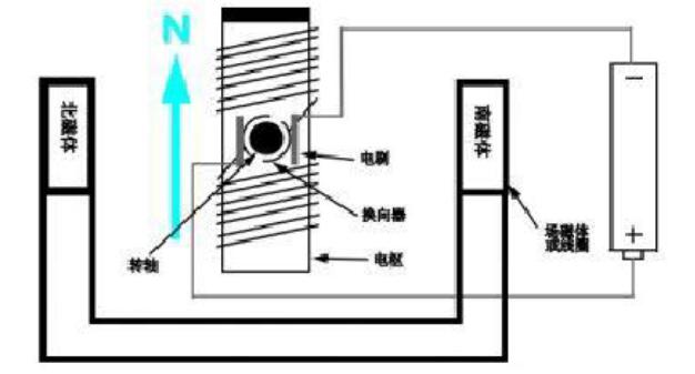
Figure 1 Simple dual-pole brushed DC motor
stator
The stator generates a fixed magnetic field around the rotor. This magnetic field can be generated by permanent magnets or electromagnetic windings. The type of BDC motor is divided by the structure of the stator or the way in which the electromagnetic windings are connected to the power supply (for the different types of BDC motors see stepper motors types).
Rotor
The rotor (also called an armature) consists of one or more windings. When these windings are excited, a magnetic field is generated. The magnetic pole of the rotor magnetic field will attract the opposite magnetic pole of the stator magnetic field, so that the stator rotates. During the rotation of the motor, the windings are excited in different orders, so that the magnetic pole generated by the rotor will never overlap with the magnetic pole generated by the stator. This conversion of the magnetic field in the rotor winding is called commutation.
Brush and commutator
Unlike other motor types (ie, brushless DC motors and AC induction motors), BDC motors do not require a controller to switch the direction of the current in the electrode windings, but instead mechanically complete the commutation of the BDC motor windings. A split-type copper sleeve, called a commutator, is mounted on the shaft of the BDC motor. As the motor rotates, the carbon brush slides along the commutator and comes in contact with different segments of the commutator. These segments are connected to different rotor windings, so when the brush is powered by the motor, a dynamic magnetic field is generated inside the motor. It is important to note that brushes and commutators are the most easily lost parts of a BDC motor due to the relative slippage between the two.
Stepper motor type
As mentioned before, various types of BDC motors are distinguished by the way in which the stationary magnetic field is generated in the stator. This section will discuss different types of BDC motors and the advantages and disadvantages of each type.
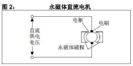
Permanent magnets
The Permanent Magnet Brushed DC (PMDC) motor is the world's most common BDC motor. This type of motor uses permanent magnets to generate a stator magnetic field. PMDC motors are commonly used in applications including fractional horsepower motors because permanent magnets are more cost effective than winding stators. The disadvantage of the PMDC motor is that the magnetism of the permanent magnet will gradually decline over time. Some PMDC motors also have windings around their permanent magnets to prevent magnetic loss. The linearity of the PMDC motor's performance curve (voltage versus speed) is very good. Current and torque have a linear relationship. Since the stator field is constant, this type of motor responds very quickly to voltage changes.
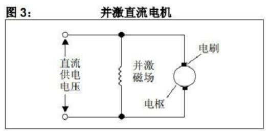
Excite
The shunt-wound brushed DC (SHWDC) motor's excitation coil is connected in parallel with the armature. The current in the excitation coil and the current in the armature are independent of each other. Therefore, these motors have excellent speed control capabilities. SHWDC motors are commonly used in applications that require five or more horsepower. In SHWDC motors, there is no problem of magnetic loss, so they are usually more reliable than PMDC motors.
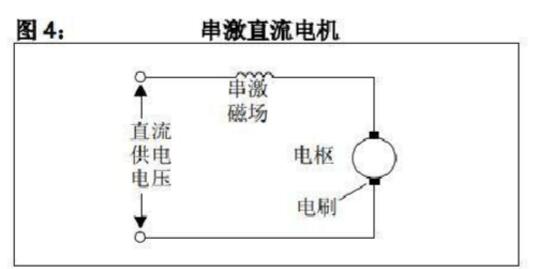
String excitation
The excitation coil of a series-wound brushed DC (SWDC) motor is connected in series with the armature. Since the stator and armature currents increase with the load, these motors are ideal for high torque applications. The disadvantage of the SWDC motor is that it does not precisely control the speed as the PMDC and SHWDC motors do.
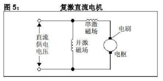
Resuscitation
Compound Wound (CWDC) motors are combinations of parallel and series motors. As shown in Figure 5, a CWDC motor can generate two types of magnetic fields, the series and the parallel. CWDC motors combine the performance of SWDC and SHWDC motors. They have greater torque than SHWDC motors and provide better speed control than SWDC motors.
Basic drive circuit
Drive circuits are used in applications where a certain type of controller is used and speed control is required. The purpose of the drive circuit is to provide the controller with a method of changing the winding current in the BDC motor. The drive circuit discussed in this section allows the controller to pulse width modulate the supply voltage of the BDC motor. In terms of power consumption, such a speed control method is much more efficient in changing the speed of the BDC motor than the conventional analog control method. Traditional analog control requires an additional varistor in series with the motor windings, which reduces efficiency. There are many ways to drive a BDC motor. Some applications only require the motor to run in one direction. Figure 6 and Figure 7 show the circuit that drives the BDC motor in one direction. The former uses low-end drivers, while the latter uses high-end drivers. The advantage of using low-side drivers is that you don't need to use FET drivers. The use of FET drivers is:
1. Convert the TTL signal that drives the MOSFET to the level of the supply voltage.
2, to provide enough current to drive the MOSFET (1)
3. Provide level translation in half-bridge applications.
Note 1: For most PICs, the second point is usually not applicable because the PIC microcontroller I/O pin can supply 20 mA.
Note that in each circuit, a diode is connected across both ends of the motor in order to prevent Back Electromagnetic Flux (BEMF) voltage from damaging the MOSFET. BEMF is generated during motor rotation. When the MOSFET is turned off, the windings of the motor are still energized and reverse current will be generated. D1 must have a suitable rating to be able to dissipate this current.
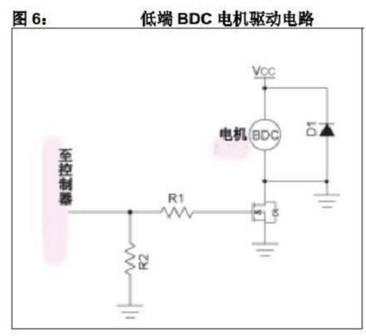
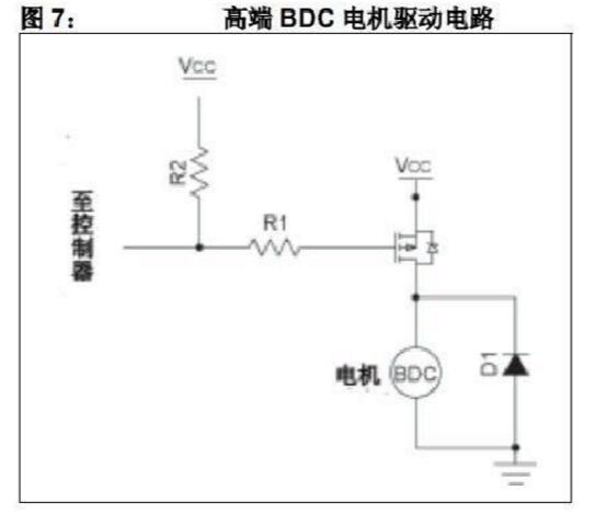
Resistors R1 and R2 in Figures 6 and 7 are important for the operation of each circuit. R1 is used to protect the microcontroller from sacrificing the current surge. R2 is used to ensure that Q1 turns off when the input pin is in three states.
The bi-directional control of the BDC motor requires a circuit called the H-bridge. The name of the H-bridge is due to the appearance of its schematic, which enables the current in the motor windings to move in both directions. To understand this, the H-bridge must be divided into two parts, or two half-bridges. As shown in Figure 8, Q1 and Q2 form a half-bridge, while Q3 and Q4 form the other half-bridge. Each half-bridge can control the turn-on and turn-off of one end of the BDC motor to the supply voltage or ground potential. For example, when Q1 turns on and Q2 turns off, the left end of the motor will be at the supply voltage potential. Turning on Q4, keeping Q3 off will ground the opposite end of the motor. The IFWD marked with an arrow shows the current flow in this configuration.
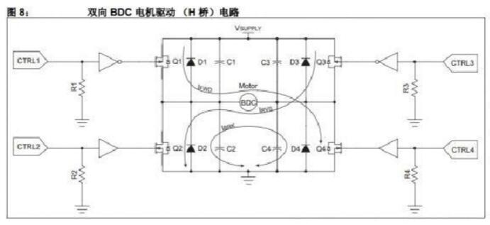
Note that there is a diode (D1-D4) across each MOSFET. These diodes protect the MOSFET from the destruction of the current spikes produced by the BEMF when the MOSFET is turned off. These diodes are needed only if the diodes inside the MOSFET are not enough to consume the BEMF current. Capacitors (C1-C4) are optional. The value of these capacitors is usually no more than 10 pF, they are used to reduce RF radiation due to the commutator arching.
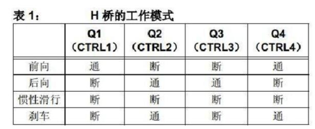
Table 1 shows the different driving modes of the H-bridge circuit. In the forward and backward modes, one end of the bridge is at ground potential and the other end is at VSUPPLY. In Figure 8, the IFWD and IRVS arrows depict the circuit paths for the forward and backward modes of operation, respectively. In coast mode, the terminals of the motor windings are left floating and the motor coasts to stop. Brake mode is used to quickly stop the BDC motor. In brake mode, the terminals of the motor are grounded. When the motor rotates, it acts as a generator. Shorting the leads of the motor corresponds to an infinite load on the motor, allowing the motor to stop quickly. The IBRK arrow depicts this
When designing an H-bridge circuit, it is necessary to consider a very important matter. When the input to the circuit is unpredictable (such as during microcontroller startup), all MOSFETs must be biased to the off state. This will ensure that the MOSFETs on each half-bridge of the H-bridge will never be turned on at the same time. At the same time turning on the MOSFET on the same half-bridge will cause a short circuit in the power supply, eventually causing damage to the MOSFET, rendering the circuit inoperable. A pull-down resistor on each MOSFET driver input will implement this function (see Figure 8 for a configuration diagram).
speed control
The speed of the BDC motor is proportional to the voltage applied to the motor. When using CNC technology, pulse width modulation (PWM) signals are used to generate the average voltage. The winding of the motor acts as a low-pass filter, so a PWM signal with sufficient frequency will produce a stable current in the motor windings. The relationship between average voltage, supply voltage and duty cycle is given by the following formula:
Formula 1: VAVERAGE = D × VSUPPLY
There is a direct relationship between speed and duty cycle. For example, if the rated BDC motor rotates at 15000 RPM at 12V, when a 50% duty cycle signal is applied to the motor, the motor will (ideally) rotate at 7500 RPM. The frequency of the PWM signal is the focus of consideration. Too low a frequency will cause the motor speed to be too low, the noise to be large, and the response to duty cycle changes to be too slow.
If the frequency is too high, the efficiency of the system will be reduced due to the switching losses of the switchgear. The rule of thumb is to modulate the frequency of the input signal in the 4 kHz to 20 kHz range. This range is high enough that the noise of the motor can be attenuated and the switching losses in the MOSFET (or BJT) can also be ignored. In general, finding a satisfactory PWM frequency for a given motor experiment is a good idea. How to use a PIC microcontroller to generate a PWM signal that controls the speed of a BDC motor? One method is to alternately flip the output pin level (1) by writing a special assembly or C code. Another method is to select a PIC microcontroller with a hardware PWM module. The modules provided by Microchip with this function are CCP and ECCP modules. Many PIC microcontrollers have CCP and ECCP modules. See the product selection guide for devices with these functional blocks.
Note 1: Microchip's application note AN847 shows an assembly code routine that uses firmware to pulse-width modulate the I/O pins.
The CCP module (abbreviation for Capture Compare and PWM) can output a 10-bit PWM signal on an I/O pin. 10-bit resolution means that the module can achieve 210 (ie, 1024) possible duty cycle values ​​in the range of 0% to 100%. The advantage of using this module is that it can autonomously generate PWM signals on the I/O pins, freeing up the processor and giving it time to complete other tasks. The CCP module only requires the developer to configure the parameters of the module. The configuration module includes setting frequency and duty cycle registers. The ECCP module (abbreviation for Enhanced Capture Compare and PWM) not only provides all the functions of the CCP module, but also can drive a full-bridge or half-bridge circuit. The ECCP module also has an auto-shutdown function and a programmable dead-band delay.
Note: Microchip's application note AN893 provides detailed instructions for configuring the ECCP module to drive a BDC motor. This application note also contains examples of firmware and driver circuits.
Feedback mechanism
Although the speed of a BDC motor is generally proportional to the duty cycle, there is no perfectly perfect motor. Heat, commutator wear, and load all affect the speed of the motor. It is a good idea to introduce some type of feedback in a system that requires precise speed control. Speed ​​control can be achieved in two ways. The first way is to use some kind of speed sensor. The second way is to use the motor-generated BEMF voltage.
Sensor feedback
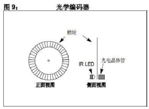
There are several sensors available for speed feedback. The most common are optical encoders and Hall effect sensors. The optical encoder consists of several components. Install a sheave on the non-drive end of the motor. An infrared LED provides the light source on one side of the wheel and a phototransistor detects the light on the other side of the wheel (see Figure 9). Light passing through the slot in the wheel turns on the phototransistor. When the shaft rotates, the phototransistor turns on and off as the light passes through the groove. The on-off frequency of the transistor characterizes the speed of the motor. In applications where the motor shifts, an optical encoder will also be used to feed back the motor position.
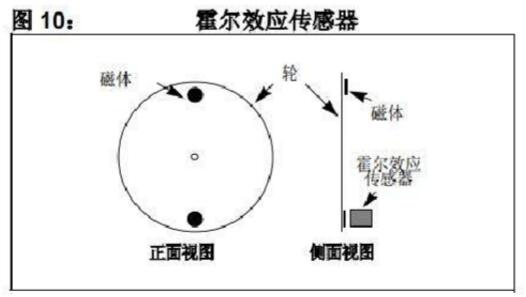
Hall effect sensors are also used to provide speed feedback. Like optical encoders, Hall-effect sensors require a rotating element on the motor and a static element. The rotating element is a wheel with one or more magnets mounted on its outer edge. The stationary sensor detects the passing magnet and generates a TTL pulse. Figure 10 shows the basic components of a Hall effect sensor.
Anti-electromagnetic flux (BEMF)
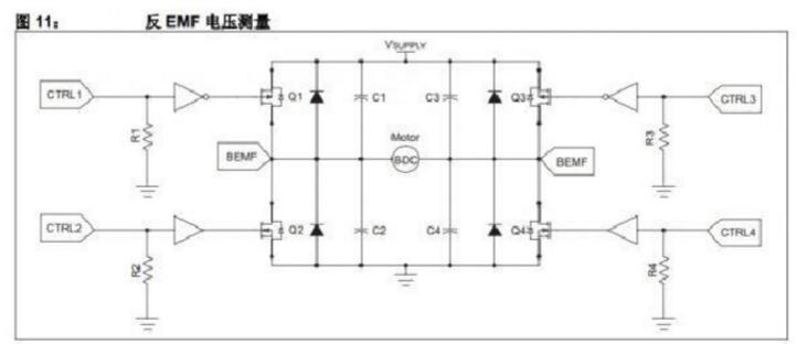
Another form of quick feedback to provide BDC motor is BEMF voltage measurement. BEMF voltage is proportional to speed. Figure 11 shows where the BEMF voltage is measured in a bidirectional drive circuit. A voltage divider is used to bring the BEMF voltage down to the 0-5V range so that it can be read by the ADC. The BEMF voltage is measured between PWM pulses when one end of the motor is left floating and the other end is grounded. In this case, the motor acts as a generator and produces a BEMF voltage proportional to the speed.
Due to different efficiency and materials, all BDC motors behave slightly differently. Experiments are the best way to determine the BEMF voltage at a given motor speed. The reflection band on the motor shaft helps the digital tachometer measure the motor's rotation speed (in RPM). Reading the digital tempo measurement BEMF voltage will obtain the relationship between the motor speed and the BEMF voltage.
Note: Microchip's application note AN893 provides examples of firmware and circuitry for reading BEMF voltages using the PIC16F684.
in conclusion
Brushed DC motors are easy to use and control, so their design cycle is short. PIC microcontrollers, especially those with CCP or ECCP modules, are ideal for driving BDC motors.
Strain/flex Reliefs And Grommets
the power Connectors we provide overmolding solutions and modular tooling.
We also offer to the OEM and distributor users a diversified line of strain / flex reliefs and grommets, such as Solid, Solid-Rib, Uniflex, Multiflex, in standard off the shelf or custom designs.
Overmolding the power connectors offers significant opportunities for cable improvements with higher pull strength not available with conventional backshells. Our technical staff is ready to help you from design and prototyping to small production run, assistance, and training.
Our team is ready to help with any of the following power connectors projects: overmolding mini fit jr. and mini-fit sr. connectors, , overmolded cables with micro fit terminations, sabre molded cable asemblies, amp duac overmolded power connectors, mate-n-lock power cables, power connector overmolding services, power connector molding, design and prototype of power cables across the board, small run molded power connecotrs , molded cable manufacturing, overmolding connectors for any power applications
Strain Reliefs And Grommets,Flex Reliefs And Grommets,Cable Strain Reliefs,Cable Flex Reliefs,Cable Grommets,Molded Strain Relief
ETOP WIREHARNESS LIMITED , https://www.oemmoldedcables.com