This blog post is the third in a series of non-RF (RF) and RF amplifier specifications. I discussed noise and two-tone distortion in the previous two blog posts. Today, we will discuss an equally important topic - the output limit of the amplifier. For amplifiers in any application, there is a limit to the swing range of the output voltage and the amount of current that can be supplied to the load. These limits are basically set by the device supply voltage, output stage architecture, and process technology limitations. Most linear amplifiers include a specification that states the maximum and minimum output voltages and maximum currents supported.
For RF-guided amplifiers such as low noise amplifiers (LNAs), RF power amplifiers (PAs), and RF gain modules, the output swing limit is typically expressed as a 1 dB gain compression point. As linear and RF amplifier speeds approach each other in modern high-speed amplifiers such as the LMH6401 gain amplifier, it is important to understand the correlation between these two specifications and how they reflect device performance.
Let's first look at the absolute output voltage and current for the largest specifications because they are the simplest. As the absolute output voltage of the amplifier increases, it will eventually reach the physical limits set by the architecture of the amplifier. This physical limit is called the maximum or minimum output voltage.
There are usually two methods for measuring the output voltage commonly used. The easiest way is to record the output voltage when you input a signal, which will cause the output to far exceed the expected output limit. From there you can see the limits of the output, but will not tell you anything about how the amplifier will work with the signals that reach these voltages.
Figure 1 shows the maximum output value of the LMH6401. When the output reaches its maximum value, it will be significantly "flattened". However, the maximum "linear" output voltage is a more efficient method of performance assurance. This is an output voltage value where the amplifier maintains its linear performance and functionality at all times.
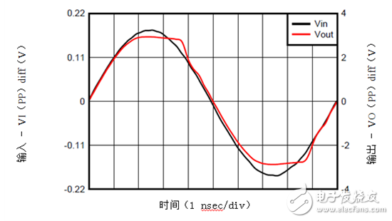
Figure 1: LMH6401 output overload
The output current specification is similar to the output voltage and typically includes an amplifier providing a "short-circuit current" for effective no-load, and a linear output current, which is conceptually the same as the linear output voltage, but is specified in terms of current output capability.
Unfortunately, the specifications for linear output voltages and currents are not standardized across the industry. The linear output voltage or current you test may have different levels of accuracy, and many different methods are beyond the scope of this blog post. For specific equipment, please refer to the Test Conditions for Output Voltages and Currents in your Amplifier Data Sheet.
The second specification, which outputs a 1dB compression point, is actually very similar to the concept of maximum linear output voltage and current. It is also known as P1dB, at which point the amplifier is ideally compressed to a 1 dB output power level. Figure 1 illustrates this concept, where the solid line represents the measured signal and the dashed line represents the ideal signal. Sometimes, some measurements compare the P1dB point to the input rather than the output, which should be considered in the calculation.
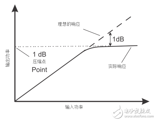
Figure 2: Example of output P1dB
Since the P1dB specification marks the 1dB gain loss point, it provides a good reference for the maximum linear output point, as opposed to the absolute maximum voltage or current. As discussed earlier in this blog post, linear measurements provide more information to ensure system performance. The P1dB specification also has the advantage of capturing maximum output power rather than just voltage or current. In other words, what you are looking at is the maximum voltage that drives a certain load, which means that P1dB measurements take into account both current and voltage effects.
Comparing the maximum output voltage/current and P1dB specifications, you can see that although the output specifications are easier to understand, they do not produce a combination limit similar to the P1dB point. The output specification tells you the voltage and current values ​​at which the output is active, but it does not explain the interaction between the two limits, just like the P1dB point. However, you can still use both specifications together and roughly estimate the combined output limits of the amplifier.
For amplifiers with only one P1dB specification, you can extract voltage and current values ​​from the measured load during the measurement, but it does not indicate the specific factors that limit the performance of the device. You need to make P1dB measurements at multiple load values ​​to fully understand the amplifier's output voltage and current limits.
the Blue Ray dvd case use to pack the dvd-r ,cd-r ,blue ray dvd-r,blue ray cd-r
Blue Ray dvd case
blue ray dvd case ,blue ray dvd box ,blue ray dvd cover
Shantou Yashidar Electronic Co.LTD , https://www.headsetswireless.com