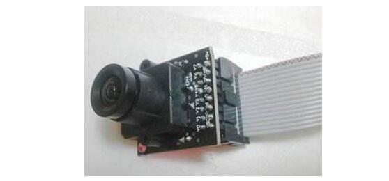
**Introduction to OV7620**
The OV7620 is a CMOS camera device that functions as a color CMOS image acquisition integrated chip. It offers high performance in a compact package, with a resolution of 640x480 and a frame rate of 30 frames per second. This sensor is widely used in various applications due to its versatility and ease of integration.
The OV7620 is a 1/3" CMOS image sensor capable of capturing both color and black-and-white images. It supports continuous and interlaced scanning modes, making it suitable for VGA and QVGA resolutions. The maximum pixel count is 664×492, with a default effective resolution of 640×480. It provides data formats such as YUV and YCrCb, along with three RGB options, which are ideal for general image acquisition systems.
**OV7620 Basic Parameters**
- Size: 33x27x24 (mm)
- Power Supply: DC +5V ±5%
- Scanning Method: Progressive/Interlaced
- Minimum Illumination: 2.5 lux at f1.4 (3000K)
- Signal-to-Noise Ratio: 48dB
- Maximum Pixel: (H) 664 x (V) 492; Default Effective Pixel: (H) 640 x (V) 480
- Data Output Format:
- YCrCb 16-bit/8-bit selectable
- 60Hz 16-bit YCrCb 4:2:2 – 640x480
- 60Hz 8-bit YCrCb 4:2:2 – 640x480
- RGB Raw Data Digital Output 16-bit/8-bit selectable
- CCIR601, CCIR656, ZV Port: Support 8/16-bit video data
- SCCB Interface: Supports up to 400 kBit/s
- YCrCb or YUV Output Format: Supports TV or monitor display
**How the Camera Works**
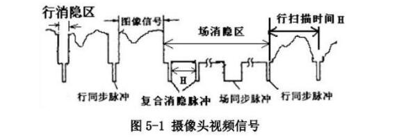
The OV7620 operates using interlaced scanning, where the image is captured line by line. When a line is scanned, the gray level of each point on the image is converted into a corresponding voltage value. This voltage is then output through the video signal terminal.
In an interlaced scan, the camera continuously scans lines on the image, producing a continuous voltage signal. After each line, there is a brief period where the voltage drops below the lowest video signal level, known as a "groove." This is called a line sync pulse, indicating the end of one line and the start of the next. The field blanking area follows, during which there are several composite blanking pulses, with one being significantly longer—this is the field sync pulse, signaling the transition between fields.
The camera captures 25 fields per second, with each field consisting of two parts: odd and even lines. This results in 50 fields per second. The odd field contains only the odd lines, while the even field includes the even lines.
**Key Metrics: Resolution and Effective Pixels**
Resolution refers to the number of sync pulses per field, with more pulses indicating higher vertical resolution. Effective pixels are often expressed as two numbers multiplied together, such as "320x240," where the first number represents the horizontal resolution, and the second indicates the vertical resolution. The effective pixel count is calculated as line resolution capability multiplied by resolution.
**Register Address and Control**
The OV7620 has a register address range from 0x00 to 0x7C, many of which are reserved. By configuring these registers, the camera can operate in different modes. For example, setting it to continuous scan and 16-bit RGB raw data mode involves writing to specific registers using the I2CSendByte() function.
The OV7620 is controlled via the SCCB (Serial Camera Control Bus) protocol, a simplified version of I2C. SCCB uses SIO-1 for the serial clock input and SIO-0 for the bidirectional data line, equivalent to SCL and SDA in I2C. The bus timing is similar to I2C, with the ACK signal being the ninth bit of a transmission unit.
**Use of OV7620**
Although many modern cameras outperform the OV7620, it remains a popular choice for learning and development. Its features and performance make it ideal for various applications, especially in embedded systems.
The OV7620 outputs data in formats like RGB565 and YUY422. One common format is YUV422, which is efficient for color image processing.
**1. What is YUV422?**
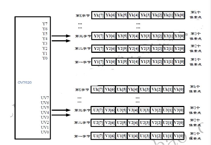
The human eye is more sensitive to brightness than to color. Therefore, RGB signals are converted to YUV, where Y represents brightness and UV represents color difference. In YUV422, the Y component is sampled at full resolution, while the UV components are subsampled, reducing data size while maintaining visual quality.
For the OV7620, there are two parallel data ports: Y[7..0] and UV[7..0]. The Y port outputs the grayscale value, while the UV port outputs the chrominance signal. The figure below illustrates the data format for a single pixel.
**2. Advantages of OV7620**
- **Voltage Compatibility:** The OV7620 is compatible with both 3.3V and 5V logic levels, making it adaptable to various microcontrollers.
- **Frame Rate:** The OV7620 operates at 60 frames per second, with a PCLK cycle of 73ns, which is easily handled by most microcontrollers.
- **Resolution:** The OV7620 supports multiple resolutions, including VGA and QVGA, with the ability to adjust settings via SCCB.
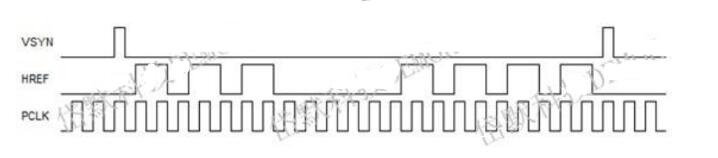
**Timing Analysis**
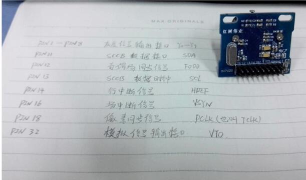
Understanding the timing of the OV7620 is crucial for effective use. Key signals include VSYNC (field sync), HREF (line sync), and PCLK (pixel clock). Monitoring these signals with an oscilloscope helps in synchronizing image capture.
**Code Examples**
Initialization of the OV7620 involves configuring GPIO pins for PCLK, HREF, and VSYNC, along with setting up DMA for efficient data transfer.
```c
void OV7620_Init() {
// Configure PCLK, HREF, VSYNC
GPIO_InitStruct1.GPIO_Pin = OV7620_PCLK_PIN;
GPIO_InitStruct1.GPIO_Mode = GPIO_Mode_IPD;
GPIO_InitStruct1.GPIO_IRQMode = GPIO_IT_DMA_RISING;
GPIO_Init(&GPIO_InitStruct1);
// Configure HREF and VSYNC
// Similar code for HREF and VSYNC
}
```
**SCCB Protocol Implementation**
The SCCB protocol is used to communicate with the OV7620. Below is a sample implementation:
```c
void sccb_init(void) {
// Initialize SCL and SDA as output
}
void sccb_start(void) {
// Generate start condition
}
void sccb_stop(void) {
// Generate stop condition
}
U8 sccb_sendByte(u8 data) {
// Send a byte over SCCB
}
```
**Example Usage**
Setting up the OV7620 with specific configurations:
```c
sccb_init();
sccb_regWrite(0x42, 0x11, 0x01); // Set resolution
sccb_regWrite(0x42, 0x14, 0x24); // Adjust timing
```
After understanding the OV7620's operation and configuration, you should be able to integrate it into your projects effectively.
Spdt Momentary Rocker Switch,16 Amp Single Pole Rocker Switch,Single Pole Double Rocker Switch
Yang Guang Auli Electronic Appliances Co., Ltd. , https://www.ygpowerstrips.com