Abstract: How to design a broadcast audio product that meets both cost control requirements and high-quality audio enjoyment to meet the demand for cost reduction and simple design in this field has become the focus of the industry. In order to realize low-cost AM/FM car radio application, this paper introduces low-cost microcontroller MC9S08QG8, integrated radio chip TEF6621, low-cost audio processing and high-fidelity power output scheme, and reduces the hardware design circuit, while describing the device selection and overall Build ideas and hardware design details. This design can meet the requirements of low power consumption, low cost, high performance and high sound quality.
This article refers to the address: http://
Keywords: car radio; AM/FM; microcontroller; MC9S08QG8; TEF6621; hardware design
As the car changes from a transit tool to a personalized consumer product that combines leisure and entertainment, consumers' demands for car entertainment continue to increase, and the automotive industry is facing strong market pressure, which needs to be reduced without sacrificing performance. Cost, this phenomenon is particularly evident in the entry-level automotive market, and consumer demand for low-cost vehicles has allowed the low-end media entertainment market to grow at an annual rate of more than 10%. AM/FM radios are especially popular for their low cost and high sound quality. How to design a broadcast audio product that meets both cost control requirements and high-quality audio enjoyment to meet the demand for cost reduction and simple design in this field has become the focus of the industry. We can imagine the continuous improvement and continuous innovation of the radio, making the development of the radio more and more.
The usual traditional radio solution consists of a frequency/amplitude radio composed of a split-integrated unit. The main components are: antenna, input loop, high-frequency amplifier circuit, mixing circuit, local oscillator circuit, intermediate frequency amplifier circuit, and frequency discrimination. Circuit, low frequency power amplifier circuit, speaker, etc. The design of the modified scheme is very complicated, and the sound quality is loud and the audio signal is seriously distorted. Evaluation in all aspects is not the best solution. This article will design a new, low-cost, RFCMOS single-chip AM/FM radio solution, a compact microcontroller with ultra-low-cost audio processing DSP and high-fidelity audio power amplifiers to achieve very few components. High-quality AM/FM car radio solution with few lines, small size and low cost.
1 device selection
In order to achieve the low-cost goal of low-end cars or ultra-applications, the first task is to select the appropriate microcontroller (MCU) and AM/FM low-IF tuner. Freescale Semiconductor's latest MC9S08QG low-end microcontroller family, with its processing core, on-chip peripherals, power-saving features and development tools, is an ideal solution for cost-, energy- and efficiency-sensitive control applications. The core device of this wireless controller design is the only 16-pin MC9S08QG8 in Freescale. The MC9S08QG8 is a highly integrated device in the Freescale 8-bit microcontroller family of high-performance, low-power HCS08 cores with built-in 8K FLASH memory, 512-byte RAM, SCI/SPI/IIC interface, and 8 Bit modulus timer module, A/D module, etc. The MC9S08QG8 MCU integrates features that are typically only available on larger, more expensive components, including background debug systems and built-in in-circuit emulation (ICE) for real-time bus capture, with a single-wire debug and emulation interface (BDM). Also included is a programmable 16-bit timer/pulse width modulation (PWM) module (TPM), one of the most flexible and economical of its kind.
Another major chip is the low-IF tuner, which is selected from NXP Semiconductors' TEF6621. The TEF6621 is NXP's highly successful RFCMOS single-chip car radio solution family. As an upgraded version of the industry's widely used TEF6601 and TEF6606, the TEF6621 tuner allows us to ensure that more exciting features are installed in a small space in a car radio system. The innovative feature of the tuner is that all key RF components include: voltage controlled oscillators, ceramic filters, IF transformers, low noise amplifiers and automatic gain control, requiring only 32 low cost passive peripherals (capacitors, Resistance, inductance and transistor). In addition, with the special large signal processing function, this low IF tuner can well support the high performance requirements of car radio applications. The car radio system based on the TEF6621 design will be an ideal radio solution due to more sophisticated weak signal processing, FM noise blanking, multipath mitigation capability for environmental interference noise, and suppression of compression noise.
The rest is the digital audio signal processing subsystem and the audio sound processing amplification output circuit. This solution uses PT2313 to process the system audio. The PT2313L audio processor has high and low bass control functions and high loudness (subwoofer) control functions. The stereo input port and its gain can be controlled by the microcontroller. In addition, it has four independent power amplifier excitation ports, and its output, balance and mute off can be controlled by the microcontroller. The volume can also be controlled by the microcontroller. The minimum step size is 1.25 dB.
TDA7388, a four-bridge car audio amplifier with ST Semiconductors, is a new technology class AB audio power amplifier designed in flexiwatt 25 package due to its high output power capability, low distortion, low output noise, mute function, low external The number of components, internal fixed gain (26 dB), no external compensation, no starter capacitors, etc., has become the first choice for high-end car radios.
The MC9S08QG8 internal IIC module realizes data communication control with the tuner TEF6621 and the audio processing and volume adjuster PT2313 through the IIC bus to realize the selection of the audio frequency and the adjustment of the audio volume. And through the MC9S08QG8 microprocessor to control the entire audio high-power part, to achieve standby (standby), shutdown (shut up) and other controls.
As for other peripheral devices, general-purpose ones, such as AM/FM antennas, liquid crystal displays using 16x2 character LCDs, and coded potentiometers for tuning, etc., are well-established technologies.
2 audio sound processing and equalization technology
With the continuous development of science and technology, broadcast programs have used more advanced technology and equipment from editing, production, transmission and transmission, and the quality of programs has been greatly improved. Nevertheless, the problem of matching the receiving antenna to the network and the noise and attenuation of the audio signal during transmission still plague the implementation of high-fidelity audio enjoyment technology, which is mainly because engineers pay little attention to the working state and setting problems of the audio processor. .
The broadcast audio signal has great nonlinearity in the processing. For the audio processing equipment, it not only includes the processing methods of compression, limitation, clipping, expansion, etc., but also the position and lead of the audio processing equipment. There are strict requirements on the length and the anti-interference ability in the high electromagnetic field and strong radiation environment.
The characteristics of audio propagation media, that is, the physical characteristics of sound waves, the recording and generation of audio, mainly include analog/digital, digital/analog conversion, data compression, and sound synthesis. The editing and processing methods of audio data are also diverse. In general, the processing methods of audio signals can be roughly divided into two categories: one is digital audio mode, and the other is analysis and synthesis.
Regular audio is a continuously changing analog signal that can be represented by a continuous curve called a sound wave. The curve of the analog signal, no matter how complex, can be decomposed into a linear superposition of a series of sine waves at any time t:
The wider the frequency band of the audio signal, the richer the audio signal component is, the better the sound quality is, and the larger the dynamic range is, the larger the relative variation range of the signal strength is, and the better the sound effect is. Figure 1 shows the dynamic range of several audio signals.
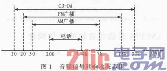
Dynamic range = 20xlog10 (maximum intensity of signal / minimum intensity of signal) (dB)
As can be seen from the figure, the frequency domain dynamic range of the three audio signals:
Signal to Noise Ratio (SNR) is an abbreviation for the ratio of useful signal to noise. Noise can be divided into ambient noise and equipment noise. The greater the signal to noise ratio, the better the sound quality.
SNR=20xlog10 (average power of wanted signal/average power of noise) (dB) (2)
The PT2313L audio processor is mainly composed of four parts of circuits. The serial bus decoding and latching circuit (Serial BusDecoder & Latchs) is used to complete the reception, decoding and latching of serial data, and to control the remaining three parts of the circuit. The input selector and gain control circuit (Input Selector & Gain Control) mainly completes the selection of the three audio sources and the control of their gain. Volume and high loudness (subwoofer), bass, treble circuit (Volume & Loudness, Bass, Treble) consists of symmetrical left and right channel circuits, mainly to control the volume, bass, bass, treble. An audio processor, also known as a digital processor. The digital processor is the processing of the digital signal. The internal structure is generally composed of the input part and the output part. The functions belonging to the audio processing part are generally as follows: the input part generally includes, input gain control (INPU TGAIN), input equalization (Several parameter equalization) adjustment (INPUT EQ), input delay adjustment (INPUT DEIAY), input polarity (also known as phase) conversion (put polarity) and other functions. The output part generally has signal input distribution routing (ROUNT), high pass filter (HPF), low pass filter (LPF), equalizer (OUTPUTEQ), polarity, gain (GAIN), delay (DELAY ), limiter start level and other functions.
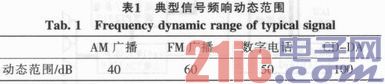
The typical tone response curve of the PT2313L audio processor is shown in Figure 2. As far as the current technical level of the audio processor is concerned, it can fully meet the requirements of high-fidelity broadcasting, so that the processed sound cannot be heard. The processing sound, that is to say, without the trace of processing, still retains the high quality of the original sound, even more pleasing, clear and pleasant than the original sound.
3 AM/FM car radio overall construction
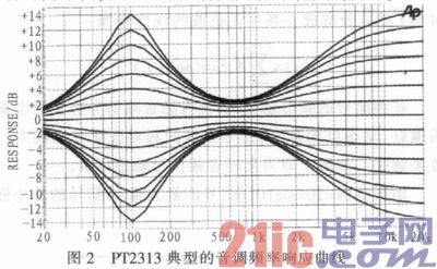
Based on the selection of the above-mentioned main components, the block diagram of the low-end car radio solution implemented in this paper is shown in Figure 3.
The interface used to configure the tuner and the audio processing IC and exchange data with the microcontroller is mainly an IIC bus interface (Inter-Integrated Circuit). The microcontroller MC9S08QG8 reads and writes the internal registers of the TEF6621 through the IIC interface (2 lines in total) (operation address: read C1H/write 0xC0H). Thereby the control and tuning operation of the TEF6621 is completed. The interface can read and write the tuner's configuration, status, and control registers to implement tuner initialization configuration and channel selection.
Since the IIC is a multi-directional control bus, the microcontroller MC9S080QG8 can simultaneously read and write the internal registers of the PT2313 through the IIC interface (operation address: read 89H/write 0x88H). Configure its internal serial bus decoding and latching circuit (Serial BusDecoder & Latchs) for serial data reception, decoding and latching, and control the input selector and gain control circuit (Input Selector & Gain Control) to complete the three-way audio source The selection and control of the volume and high loudness (subwoofer) consisting of symmetrical left and right channel circuits,
Bass, treble circuit (Volume & Loudness, Bass, Treble), complete control of the volume, bass, bass, treble control speaker attenuation and silence circuit (Speaker Att, Mute) control, can be sent to the left channel front, back The control and the amplitude of the excitation signal amplitude of the front and rear four-channel speaker amplifier circuits of the right channel. At the same time, the microcontroller MC9S08QG8 performs mute control (standby control Standby) on the TDA7388 through a general-purpose I/O interface GPIO.
The microcontroller MC9S08QG8 reads the code potentiometer. The rotary code potentiometer has three functions: left turn, right turn, and press. 4, 5 feet are the switch wiring in the middle, 1, 2, 3 feet are generally grounded in the middle 2 feet, 1 and 3 feet pull-up resistor, when left turn, right turn knob, there are 1 and 3 feet The pulse signal is output. The MCU completes counting the pulses of pins 1 and 3 through the general-purpose I/O interface GPIO. The 5-pin of the coding switch is grounded. After the 4-pin is pulled up, it is connected to the MCU interrupt request (IRQ) signal, and the IRQ pin will generate a falling edge transition. After the IRQ is generated, the microcontroller immediately reads the current state of the system, determines whether to initialize the tuner and turn on the sound and wake up the amplifier, or mute and put the amplifier in standby.
The microcontroller MC9S08QG8 completes the connection to the LCD display and buttons through the general-purpose I/O interface GPIO, where the LCD data lines are provided separately by the MCU (a total of 4 lines), and the LCD control lines are provided separately by the MCU (3 lines total).
BDM program download and online debugging only occupy the single line 1 line of the MCU, which is necessary at the beginning of the design, but when the debug download is completed, the lead can also be used as a normal I/O or used.
4 specific design of the hardware circuit
According to the previous device selection and overall construction considerations, the specific design circuit of the AM/FM car radio completed in this paper is shown in Fig. 4. Most of the pins of the MC9S08QG8 microcontroller (MCU) have multiple functions. In the circuit design, the MC9S08QG8 is used as the control core to realize various control such as display, tuning, audio sound, and power amplifier output.
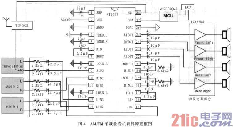
The schematic diagram of the AM/FM car radio application here is divided into three parts. The first part is the basic connection required for the MC9S08QG8 MCU. The second part is the TEF6621 tuner and antenna receiving circuit, the third part is the audio processing and power amplifying output circuit composed of PT2313 and TDA7388, and the fourth part is the human-computer interaction circuit of 16x2 LCD and code potentiometer.
The standard voltage of the car battery is 12/24 V. In this design, the DC-DC voltage adjustment circuit is used to output 1 channel 9 V voltage and 1 channel 5 V voltage. The microcontroller, display part and other low voltage peripheral parts are powered by 5 V. The digital voltage, the tuner TEF6621 and the audio chip PT2313 are powered by 9 V, and the power amplifier TDA7388 is powered by the car battery. The clock circuit of the MCU does not need an external crystal oscillator, and directly uses the clock that is built in the MCU. The TEF6621 tuner, PT2313, TDA7388 and its peripheral circuits use the minimum hardware requirements for the work provided in the data sheet. The connection between the MCU and the TEF6621 tuner and PT2313 is connected according to the standard IIC mode. The MCU is the master, and the TEF6621 and PT2313 are the slaves. The SDA and SCL signal lines are basically configured and operated on the two devices through different slave addresses to realize tuning. With tuning function.
MCU's 8K FLASH and 512 bytes of memory resources are sufficient for basic radio control. In addition, if further expansion of functions is required on the basis of this system, the on-chip resources are tight, and Freescale also provides pin-to-pin compatibility. Low-cost upgrade solution such as MC908QG16/32.
5 Conclusion
Only a Freescale MC9S08QG8 low-end microcontroller is used in the article. Together with the integrated single-chip AM/FM tuner and audio power amplifier circuit and few connection lines and hardware resources, it has complete tuning, tuning and man-machine. 4x41W high-quality, low-cost car radio with interactive features, which means that in-vehicle multimedia applications do not always require high-performance microprocessors and expensive high-fidelity processing audio devices, low-end microcontrollers and single-chip tuning The solution also meets the basic requirements of a car radio multimedia system, thereby reducing the cost of the car audio solution. At the same time, the car radio realized in this paper has the characteristics of low power consumption, few components, low cost, high performance, excellent sound quality and sufficient function. It is a streamlined solution for low-end vehicle car radio applications.
Various Puffs Vape,Disposable Vape Etsy,Allo Disposable Vape,Various Puffs Vape Atomizer
Lensen Electronics Co., Ltd , https://www.lensenvape.com