**1. Introduction**
With the rapid advancement of Internet of Things (IoT) technology, one of its key applications is the transmission of data collected by various sensor nodes to users' mobile devices or personal computers via the internet. To meet this growing demand, a versatile system is required that can function as both a coordinator in a wireless sensor network and a gateway for remote GPRS communication and network connectivity.
In response to these requirements, this design utilizes the STM32F417 microcontroller as the central processing unit. The on-chip μC/OS-II real-time operating system manages the device's operations, while the uIP protocol stack handles TCP/IP communication. The main device also includes a keyboard and display interface, allowing local configuration and remote adjustments through a PC. The GPRS module is connected via a serial port to the embedded master device, enabling it to communicate with the wireless coordinator. This coordinator, using ZigBee wireless communication, receives commands from the main device and relays them to the sensors, ensuring efficient data collection and transmission.
**2. System Hardware Design**
The embedded gateway system consists of an embedded master device, a GPRS module, a wireless coordinator, and a router. A block diagram of the system is shown in Figure 1.
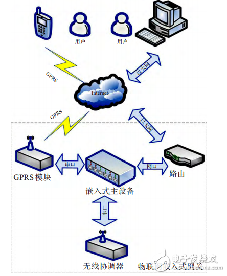
**Figure 1: Embedded Gateway System Block Diagram**
The embedded master device connects to the router through a network port, while the GPRS module is interfaced via a serial port using AT commands for control. The serial port also allows the master device to send commands to the wireless coordinator, which in turn communicates with the sensor nodes using the ZigBee protocol.
**2.1. Embedded Master Device Hardware Design**
The hardware platform of the embedded device is based on the STM32F417 microcontroller, supported by peripheral circuits such as a liquid crystal display (LCD), network port driver, keyboard interface, and serial port driver. The hardware block diagram is illustrated in Figure 2.
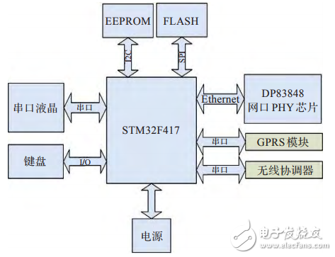
**Figure 2: Embedded Main Device Hardware Circuit Block Diagram**
This design employs a serial LCD, which simplifies the driving circuitry and only requires serial commands for operation. Display pages and controls can be stored in the LCD’s flash memory, and a graphical user interface (GUI) is developed according to the system’s needs. The keyboard provides local configuration options for the gateway.
The STM32F417 features an integrated MAC module, requiring the addition of a PHY chip to enable network communication. The underlying network driver interacts with the PHY chip, while the uIP protocol stack manages TCP/IP functions. The GPRS module is controlled via the serial port using AT commands to connect to the network, send messages, and manage power states. Similarly, the wireless coordinator is managed through the serial port and a custom communication protocol, ensuring seamless integration within the IoT system.
Off-Grid Solar Inverter,Mppt Charger,Multi-Function Inverter,High Frequency Inverters
Shenzhen Unitronic Power System Co., Ltd , https://www.unitronicpower.com