Simple design and manufacture of servo control circuit
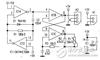
This circuit is composed of a negative pulse oscillator, made up of NAND gates IC1A and IC1D, and an RS flip-flop formed by NAND gates IC1B and IC1C. The servo control signal is taken from pin 6 of the RS flip-flop.
The oscillator generates a negative pulse train with a frequency of approximately 50 Hz. These short pulses are fed into the flip-flop's input and trigger it every 20 milliseconds. When a negative pulse reaches the trigger input (pin 4), the output of IC1C drops to a low state. This causes capacitor C3 to discharge through P1, resetting the flip-flop’s state. As a result, the output of IC1B returns to a low level, and the cycle repeats every 20 ms. The recovery time of the flip-flop is adjustable via P1, allowing for fine-tuning of the system’s response.
Servo controllers are commonly used in closed-loop control systems that allow precise positioning and speed control. They typically use pulse-width modulation or analog signals to regulate motor movement. These systems often incorporate PID (Proportional-Integral-Derivative) control for both speed and torque. A key feature of servos is their feedback mechanism, which continuously compares the actual output with the desired input, ensuring high accuracy and stable performance.
A closed-loop control system, also known as a feedback control system, operates by using both a forward path and a feedback path to create a loop. This type of system includes power amplification and feedback, enabling the output variable to closely follow the input command. After a numerical control device sends a command pulse, the command value is compared with the actual position. If the machine table hasn’t moved, the servo motor starts rotating, driving components like gears, ball screws, and nuts to move the table. Once the position sensor measures the actual displacement, it feeds this information back to the comparator in the numerical control unit. The difference between the command and feedback signals is amplified and used to adjust the motor until the error is zero, at which point the table stops. This system is known as a closed-loop servo system.
With the component values shown in the diagram, the recovery time of the RS flip-flop can be adjusted from 0.6 ms to 2 ms using P1, resulting in a corresponding rotation of the servo motor by 120 degrees.
Biconical Antenna ,Log Periodic Antenna,Marine Vhf Antenna Types
Mianyang Ouxun Information Industry Co., Ltd , https://www.ouxunantenna.com