In general, if the heat generated by the LED when the light is emitted cannot be derived, the junction temperature of the LED will be too high, thereby affecting the product life cycle, luminous efficiency, and stability, and the LED junction temperature, luminous efficiency and lifespan Relationships, the following will use the relationship diagram for further explanation.
1, LED heat dissipation
According to different packaging technologies, the heat dissipation methods are also different, and various heat dissipation methods for LEDs can be approximated as follows:
Thermal path description:
(1) Heat dissipation from the air (2) Heat energy is directly derived from the System circuit board (3) Heat energy is extracted via the gold wire (4) In the case of eutectic and Flipchip processes, thermal energy is derived from the through-hole to the system board. The LED die (Die) is connected to its substrate (LED substrate) by gold, eutectic or flip chip to form an LED chip, and then the LED chip is fixed on the system circuit board. Therefore, the LED may be cooled by direct heat dissipation from the air or through the LED die substrate to the system board and then to the atmosphere. The rate of heat dissipation from the system board to the atmosphere depends on the design of the entire light fixture or system. However, the bottleneck of heat dissipation in the entire system at the present stage is mostly the conduction of heat from the LED die to its substrate to the system circuit board. The possible heat-dissipation path in this part: one is to directly dissipate heat from the die substrate to the system circuit board. In this heat-dissipation path, the heat dissipation capability of the LED die substrate material is an important parameter. On the other hand, the heat generated by the LED also passes through the electrode metal wires to the system circuit board. Generally speaking, under the condition that the gold wire is used for electrode bonding, the heat dissipation is limited by the relatively slender geometry of the metal wire; therefore Recently, Eutectic or Flipchip bonding methods have been adopted. This design significantly reduces the length of the wire and significantly increases the cross-sectional area of ​​the wire. As a result, the efficiency of heat dissipation from the LED electrode wire to the system board will be effective. Promote. Through the explanation of the above heat-dissipation path, it can be known that the selection of the heat-dissipating substrate material and the encapsulation manner of the LED die occupies a very important part in the management of the LED heat dissipation, and the following section will outline the outline of the LED heat-dissipating substrate.
2, LED heat-dissipating substrate
The LED heat-dissipating substrate mainly uses the heat-dissipating substrate material itself to have better thermal conductivity, and the heat source is led out from the LED die. Therefore, from the description of LED heat dissipation methods, LED heat-dissipating substrates can be subdivided into two categories, namely, LED die substrates and system circuit boards. These two different heat-dissipating substrates carry LED die and LED chips respectively. The heat energy generated when the LED die emits light passes through the LED die to heat the substrate to the system circuit board, and then is absorbed by the atmospheric environment to achieve the effect of heat dissipation.
2.1 System Board System Board is mainly used as the LED heat dissipation system, and finally the heat energy is conducted to the heat sink fins, the shell or the atmosphere. In recent years, the production technology of printed circuit boards (PCBs) has become very sophisticated. The system circuit boards of early LED products are mainly PCBs. However, as the demand for high-power LEDs increases, the heat dissipation capacity of PCB materials is limited, making it impossible to apply them. For its high-power products, in order to improve the heat dissipation of high-power LEDs, a high thermal conductivity coefficient aluminum substrate (MCPCB) has recently been developed. The use of metal materials with better heat dissipation characteristics has achieved the purpose of heat dissipation for high-power products. However, with the continuous development of LED brightness and performance requirements, although the system board can effectively dissipate the heat generated by the LED chip to the atmosphere, the heat generated by the LED die can not be efficiently conducted from the die to the system circuit. The board, in other words, when the LED power is increased more efficiently, the heat sink bottleneck of the entire LED will appear on the LED die heat sink substrate.
2.2 LED die substrate The LED die substrate is mainly used as the medium for the thermal energy between the LED die and the system circuit board, and is combined with the LED die by the process of wire bonding, eutectic or flip chip. Based on heat dissipation considerations, the current market for LED die substrates is mainly based on ceramic substrates. The circuit preparation methods can be roughly divided into three types: thick-film ceramic substrates, low-temperature co-fired multilayer ceramics, and thin-film ceramic substrates. Traditional high-power LED devices mostly use a thick film or a low-temperature co-fired ceramic substrate as a crystal heat-dissipating substrate, and then combine the LED crystal grains with a ceramic substrate by using gold wires. As mentioned in the introduction, this gold wire connection limits the heat dissipation along the electrode contact. Therefore, in recent years, major manufacturers at home and abroad have all worked hard to solve this problem. There are two ways to solve this problem. One is to find a substrate material with a high heat dissipation coefficient to replace aluminum oxide, which includes a tantalum substrate, a tantalum carbide substrate, an anodized aluminum substrate, or an aluminum nitride substrate. Among them, a material semiconductor for tantalum and a tantalum carbide substrate. The characteristics have caused it to face severe challenges at the current stage, and the anodized aluminum substrate is susceptible to cracking due to insufficient strength of the anodized oxide layer, which limits its practical application. Therefore, at this stage, Aluminum nitride is used as a heat-dissipating substrate for more mature and commonly accepted substrates; however, it is currently limited to aluminum nitride substrates that are not suitable for conventional thick-film processes (the material must be subjected to atmospheric heat treatment at 850°C after printing in silver paste, so that The material reliability problem arises. Therefore, the aluminum nitride substrate line needs to be prepared by a thin film process. The aluminum nitride substrate prepared by the thin film process greatly accelerates the performance of heat from the LED die through the substrate material to the system circuit board, thereby greatly reducing the heat burden caused by the LED die via the metal line to the system circuit board, thereby achieving high heat dissipation. Effect.
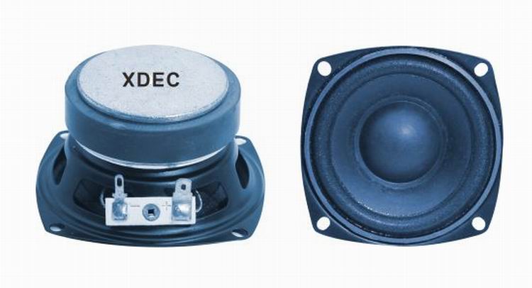
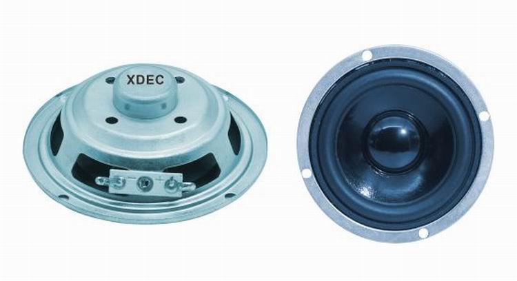
3"~5" speaker (76~128mm)
1)3" Speaker 78Mm Speaker
2)3.5" Speaker 89Mm Speaker
3)3.6" Speaker 91Mm Speaker
4)4" Speaker 102Mm Speaker
5)5" speaker 128mm speaker


FAQ
Q1. What is the MOQ?
XDEC: 2000pcs for one model.
Q2. What is the delivery lead time?
XDEC: 15 days for normal orders, 10 days for urgent orders.
Q3. What are the payment methods?
XDEC: T/T, PayPal, Western Union, Money Gram.
Q4. Can you offer samples for testing?
XDEC: Yes, we offer free samples.
Q5. How soon can you send samples?
XDEC: We can send samples in 3-5 days.
3"~5" Speaker 76~128mm
3" Speaker 78Mm Speaker,3.5" Speaker 89Mm Speaker,3.6" Speaker 91Mm Speaker,4" Speaker 102Mm Speaker
Shenzhen Xuanda Electronics Co., Ltd. , https://www.xdecspeaker.com