Non-polar wiring design of RS422 / RS485 network
Abstract: In the RS422 / 485 network, the design method of the module can receive any polarity DC power supply and bus signal. This method allows two signal lines or DC power lines to be connected in any polarity during transmission, tolerating reverse connection errors in wiring construction, making the construction of the project much more convenient
Keywords RS422, RS485, non-polar split-continuous box rectifier bridge, differential Manchester
1. Question raised
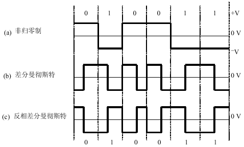
Many current measurement and control systems are interconnected using RS422 or RS485 buses. The RS422 / 485 bus signal is transmitted by 4 (2) polar differential signals, which cannot be reversed. When the network transmission distance is long or there are many nodes, there will be a lot of junction boxes on the line, it is easy to reverse the signal line during the transmission, resulting in the signal cannot be transmitted normally. Although the fault point can be detected, it is also a very time-consuming task when there are many junction boxes. For the convenience of wiring, the number of junction boxes is often greater than the number of modules on the bus. For indoor systems, PVC lines are usually added to the network lines or even buried in the wall; for outdoor systems, the lines are generally overhead or underground, which makes it difficult to find and correct the reverse connection problem. On the other hand, for the convenience of construction, it should also be allowed to connect freely on the way, regardless of polarity. For this reason, each module needs to be able to receive both the normal-phase signal shown in FIG. 1 (b) and the RS422 and RS485 signals whose polarities may be reversed as shown in FIG. 1 (c).

Figure 1 Change in the signal waveform at the receiving end caused by the wrong connection of the transmission line
For those RS422 / 485 systems that use a baseband signal without any modulation and modulation to transmit data, the wiring error in Figure 1 will cause the recipient to fail to receive the data correctly; but if the signal is properly modulated, even if the wiring appears on the way Incorrect, the receiver can still receive the data correctly, that is, it can be wired without polarity in the wiring construction.
The following gives the design method of non-polar connection when using unmodulated signal and modulated signal to transmit data. Let us first discuss the use of uncoded modulated signals.
2. Non-polar wiring design of RS422 signal line
The RS422 bus uses separate signal lines for transmission and reception, each with two signal lines. In order to enable the RS422 receiver to receive the signals of two polarities from the bus, see Figure 1 (b) and Figure 1 (c), the wiring error must be detected first, and then the wiring error should be corrected. Here we hope to correct the wiring error through the network module circuit, rather than correct the wrong transmission line connection.
(1) Manual correction method
For the UART of the MCU, when there is no signal transmission, the TX pin is "1" level, therefore, the A terminal of the RS422 driver will be high level, and the B terminal is low level. At this time, in the A of the receiving module The terminal should also be a fixed high level. In the circuit in Figure 2, an LED is connected between a receiving end and GND, so that it can be judged whether the end is connected to the sending end A or the sending end B, and then manually adjust the module through the 4-bit dial switch SW RS422 driver receiving input connection in the bus and receiving module.

Figure 2 Non-polarity receiving circuit in RS422 bus transmission
The manual correction method requires the sending module to cooperate on the software. During the adjustment, the sender cannot send data, that is, the differential voltage on the bus is fixed. Although this method is troublesome, in some cases, it is easier than checking and correcting the circuit.
(2) Automatic correction method
If an electromagnetic relay (or analog switch) is used to replace the coding switch SW between the bus input terminal and the RS422 driver, you can automatically control the switching of buses A and B through software. Checking whether there is an error in wiring can also be done through software. As long as the sending end sends a fixed content data agreed with the receiver, if the receiver cannot receive it correctly, it indicates that the wiring is wrong, and the relay is controlled to switch the bus connection; otherwise, it is not switched. It must be noted that when using analog switches, attention should be paid to the effect on line impedance and transmission speed.
3. Non-polar wiring design of RS485 signal line
The sending and receiving signals in the RS485 bus share a pair of lines, and the drivers used can be divided into two categories: one is a driver like SN75176, and the Rx and Tx signals have been connected together within the driver; the other is using RS422 driver, such as sending and receiving using 2 chips, such as SN75177 (receive driver) plus SN75178 (transmit driver), or transceiver driver integrated on one chip, such as SNLBC75179, MAX488, MAX490, etc., in this case, Short-circuit the non-inverting end of the transceiver on the circuit board. For the latter (using a driver with independent transceiver pins), the method of non-polar design is still similar to the RS422 mode; for the former, because the non-inverting end of the transceiver signal has been short-circuited inside the driver, it is impossible to add a circuit to the receiving driver, and it can not reach the electrode The purpose of sexual signal transmission.
It can be seen that in the RS485 network, the module must use a driver with independent transceiver pins to add a non-polar design circuit.
4. Restrictions on use
The above method is only suitable for point-to-multipoint master-slave RS422 / 485 network. For the RS422 network, the receiving driver in the main module cannot be modified, but should be adjusted to the sending end of the sending module. Because in the case of sending from the module and receiving by the main module, the connection between some modules and the main module may be correct, and the connection between some modules and the main module may be wrong. For the RS485 network, as long as the adjustment circuit is added to the driver receiving end of the slave module.
For the RS422 / 485 network where each module communicates equally, the wiring between a module and other modules may be both correct and incorrect, so it is corrected by this method.
5. Adopt modulated signal transmission to eliminate signal polarity
Using the above 2 methods (manual setting or software automatic configuration) so that the module can receive signals of any polarity is feasible, but there are still some troubles: manual setting will still bring inconvenience to construction, and automatic configuration will increase the complexity of software design Degrees, reducing reliability. In addition, the above method is only applicable to the point-to-multipoint master-slave communication network, and cannot be used for the peer-to-peer network.
Another method to eliminate the polarity of the signal is to transmit it after encoding and modulating the signal, so that the modulated signal has no polarity requirement. In the field of data transmission, the most commonly used non-polar signal modulation method is to use differential Manchester encoding, and its waveform is shown in Figure 3.
The encoding principles of differential Manchester encoded signals are:
â—‡ Always invert the signal in the middle of the signal bit;
â—‡ The signal polarity is not changed at the beginning of the signal bit, indicating logic "1";
â—‡ Change the signal polarity at the beginning of the signal bit, indicating logic "0".
It can be seen that the signal encoded by the differential Manchester, see Figure 3 (b), after being converted into an inverted waveform due to a wiring error, see Figure 3 (c), still conforms to this definition, so that the original data signal can be demodulated .

Figure 3 Differential Manchester encoded signal and its inverse
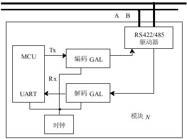
In order to implement differential Manchester encoding in the RS422 / 485 network, an encoding circuit needs to be added between the UART and RS422 / 485 chip. Differential Manchester encoding is a self-synchronizing encoding and therefore requires a clock. For the UART working in asynchronous mode, you can use the GAL device to complete the encoding and decoding, but the baud rate clock and the encoding circuit clock used to control the asynchronous transmission of the UART must use the same clock source. The implementation block diagram shown in FIG. 4 is given below, and the specific implementation circuit will not be described in detail here. You can also use a dedicated chip to complete the encoding and decoding, such as Echelon's FTT-10A transceiver. The transceiver performs differential Manchester code modulation on the signal and transmits it (including an isolation transformer).

Figure 4 Using differential Manchester encoding to generate a non-polar signal
6. Non-polar connection design of DC power supply
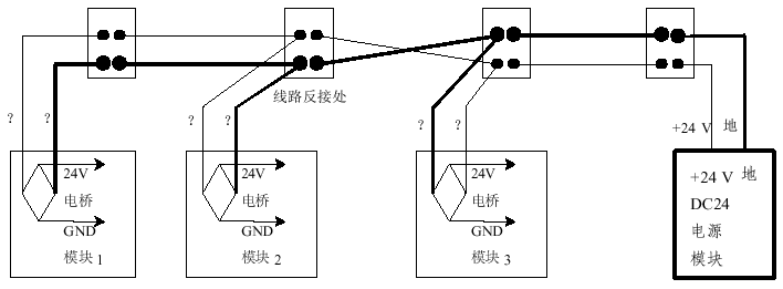
In the RS422 / 485 network, centralized +5 V, +12 V or +24 V DC is often used to supply power to all modules. If the line is long, a +24 V power supply is generally used, and when shorter, +5 V or +12 is used V power supply. Like the signal line, the power line also has the problem of reverse connection. For the same purpose and reason, the module should also be able to use the input power in two cases of normal phase and reverse phase wiring. Unlike the signal, although the two power lines may be reversed, the potential difference between the lines is always a polarity, either positive or negative. Therefore, a rectifier bridge can be added at the power input of the module. The output can always get positive +24 V or +12 V, +5 V voltage for its own use, as shown in Figure 5.

Figure 5 Nonpolar power receiving circuit of centralized DC power supply network
Flexible Welding Cable,Insulated Middle Voltage Cable,Single Core Welding Cable,Insulated Flexible Welding Cable
Huayuan Gaoke Cable Co.,Ltd. , https://www.bjhygkcable.com