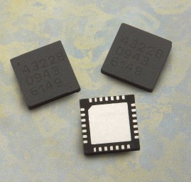
The Class A transistor power amplifier has a warm and sweet tone, which makes people tempted. However, the temperature rise of Class A power amplifiers is relatively high. If ordinary bipolar transistors are used, the temperature stability is poor, debugging is difficult, and it is also worrying during use. This article introduces the Class A amplifier of the output stage using Sanken product SAP15N / P audio pair tube. SAP15N / P output current 15A, withstand voltage 160V, power 150W, junction temperature 150 ℃. The transistor has a built-in temperature compensation diode array to solve the technical problem of temperature compensation delay in the power amplifier circuit. Its temperature compensation diode is placed in the center of the transistor chip, which can quickly and synchronously detect the temperature change of the transistor and correct the bias current To keep it constant. The Class A power amplifier made by ordinary bipolar transistors has a longer time for the amplifier to stabilize due to temperature changes. It is often stable after being energized for half an hour, and the bias current will also change with the temperature. . In actual use, it will take half an hour for the machine to be able to hear the real class A tone. The SAP15N / P pair tube is used. Due to the consistency of its internal temperature rise and compensation, the amplifier enters a stable state after a few minutes of energization, and its efficiency is high, and the work is stable and safe. Therefore, it can be said that the SAP15N / P pair is the best partner of the Class A power amplifier. In addition, SAP15N / P has many advantages such as good linearity of operation, small saturation voltage drop, and high power utilization. In addition to the temperature compensation diode, SAP15N / P has its own internal front-end driving transistor and emitter 0.22Ω resistor, which has a very high cost performance. Figure 1 is the outline drawing and internal electrical schematic of SAP15N / P. It has 5 pins. There is a PN junction diode inside its NPN side, and five Schottky diodes inside the PNP side for temperature compensation. When in use, add a variable resistor between the diode of the NPN tube and the Schottky diode of the PNP tube to adjust the no-load current.
figure 1
figure 2
working principle
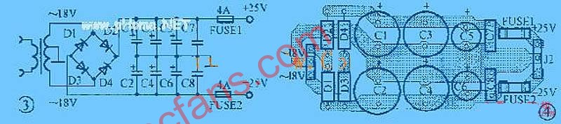
Figure 2 shows the power amplifier circuit using Class A mono design. The power amplifier has temperature detection and protection functions, and also has the characteristics of DC midpoint servo. The input stage uses a common source-common circuit composed of field effect twin tubes V1 / V2 (K389 / J109) and transistors V3 ~ V6. The circuit has low high-frequency distortion, large dynamic range, and high signal-to-noise ratio. In the second voltage amplification stage, V15 and V16 form a two-stage push-pull cascade circuit, V15 / V7 and V16 / V8 respectively form ideal current sources, current amplification is completed by V7 and V8, and voltage amplification is by V15 / V16 carry out. The speaker protection circuit adopts Toshiba speaker protection integrated circuit TA7317 (IC3), in which VD6 is the power supply detection of the shutdown noise suppression, which is connected to the AC end of the transformer. V12 and VD8 constitute the relay power supply. Field effect integrated IC1A in dual op amp IC1 (LF353) performs DC midpoint servo to stabilize the midpoint potential; IC1B and V13, temperature detection switch SW2 and optocoupler IC2 form a temperature detection and protection action circuit. The temperature switch contact is a normally closed contact with an operating temperature of 90 ° C. When used, it is fixed on the radiator with a screw to detect the temperature. Under normal circumstances, the contact of the temperature switch SW3 is closed, the voltage of the ⑤ pin of IC1B is higher than the ⑥ pin, the ⑦ pin outputs a high level, V13 is turned on, its collector is low, and the photocoupler IC2 has no current through; When the temperature of the radiator reaches 90 ℃, SW3 is disconnected, the voltage of ⑤ pin of IC1B is lower than the voltage of ⑥ pin, ⑦ pin outputs low level, V13 is cut off, its collector is high level, and current flows through ①and ② terminals of IC2 , Causing the ③ and ④ terminals to be turned on, at this time the resistor R51 shunts the excitation signal, thereby reducing the quiescent current of the final stage, and the working state is changed from class A to class A, thereby reducing the operating temperature of the transistor and ensuring its safety. IC1 and VD7 also form a self-holding circuit. When the temperature protection circuit is activated, the comparative voltage of IC1B's ⑤ pin is clamped to a low level, so that the power amplifier maintains the class A and B working state. After the temperature protection action, it will automatically restore the working status of Class A after it is turned off and then turned on. SW1 is a manual selection switch for the working mode of Class A or Class A, which can be set manually. SW1 is closed for Class A amplification, and SW1 is open for Class A and Class B amplification. When the light-emitting diode LED is on, it indicates that the power amplifier is working in the class A and B state. The temperature of Class A power amplifiers is relatively high. With temperature detection and protection, there will be no worries about "there is nothing in the sky". In addition, the switch SW3 can select whether the final stage uses large loop negative feedback. The power supply of the power amplifier excitation level is provided by the ± 50V power supply on the circuit board. In order to save volume, it is convenient to install the circuit board (250 × 80mm) close to the radiator vertically, and the final stage rectifier filter is not on the power amplifier board. In Figure 2, the electrical schematic diagram of the final stage power supply is omitted.
Circuit debugging
In order to obtain a larger dynamic range, the output current of the input stage is 2.5mA, and the potentiometer R1 is adjusted to reduce the voltage on R8 to 3V; at this time, the second-level voltage sound square
The Class A transistor power amplifier has a warm and sweet tone, which makes people tempted. However, the temperature rise of Class A power amplifiers is relatively high. If ordinary bipolar transistors are used, the temperature stability is poor, debugging is difficult, and it is also worrying during use. This article introduces the Class A amplifier of the output stage using Sanken product SAP15N / P audio pair tube. SAP15N / P output current 15A, withstand voltage 160V, power 150W, junction temperature 150 ℃. The transistor has a built-in temperature compensation diode array, which solves the technical problem of temperature compensation delay in the power amplifier circuit. Its temperature compensation diode is placed in the center of the transistor chip, which can quickly and synchronously detect the temperature change of the transistor and correct the bias current. To keep it constant. The Class A power amplifier made by ordinary bipolar transistors has a longer time for the amplifier to stabilize due to temperature changes. It is often stable after being energized for half an hour, and the bias current will also change with the temperature. . In actual use, it will take half an hour for the machine to be able to hear the real class A tone. The SAP15N / P pair tube is used. Due to the consistency of its internal temperature rise and compensation, the amplifier enters a stable state after a few minutes of energization, and its efficiency is high, and the work is stable and safe. Therefore, it can be said that the SAP15N / P pair is the best partner of the Class A power amplifier. In addition, SAP15N / P has many advantages such as good linearity of operation, small saturation voltage drop, and high power utilization. In addition to the temperature compensation diode, SAP15N / P has its own internal front-end driving transistor and emitter 0.22Ω resistor, which has a very high cost performance. Figure 1 is the outline drawing and internal electrical schematic of SAP15N / P. It has 5 pins. There is a PN junction diode inside its NPN side, and five Schottky diodes inside the PNP side for temperature compensation. When in use, add a variable resistor between the diode of the NPN tube and the Schottky diode of the PNP tube to adjust the no-load current.
working principle
Figure 2 shows the power amplifier circuit using Class A mono design. The power amplifier has temperature detection and protection functions, and also has the characteristics of DC midpoint servo. The input stage uses a common source-common circuit composed of field effect twin tubes V1 / V2 (K389 / J109) and transistors V3 ~ V6. The circuit has low high-frequency distortion, large dynamic range, and high signal-to-noise ratio. In the second voltage amplification stage, V15 and V16 form a two-stage push-pull cascade circuit, V15 / V7 and V16 / V8 respectively form ideal current sources, current amplification is completed by V7 and V8, and voltage amplification is by V15 / V16 carry out. The speaker protection circuit adopts Toshiba speaker protection integrated circuit TA7317 (IC3), in which VD6 is the power supply detection of the shutdown noise suppression, which is connected to the AC end of the transformer. V12 and VD8 constitute the relay power supply. Field effect integrated IC1A in dual op amp IC1 (LF353) performs DC midpoint servo to stabilize the midpoint potential; IC1B and V13, temperature detection switch SW2 and optocoupler IC2 form a temperature detection and protection action circuit. The temperature switch contact is a normally closed contact with an operating temperature of 90 ° C. When used, it is fixed on the radiator with a screw to detect the temperature. Under normal circumstances, the contact of the temperature switch SW3 is closed, the voltage of the ⑤ pin of IC1B is higher than the ⑥ pin, the ⑦ pin outputs a high level, V13 is turned on, its collector is at a low level, and no current passes through the photocoupler IC2; When the temperature of the radiator reaches 90 ℃, SW3 is disconnected, the voltage of ⑤ pin of IC1B is lower than the voltage of ⑥ pin, ⑦ pin outputs low level, V13 is cut off, its collector is high level, and current flows through ①and ② terminals of IC2 , Causing the ③ and ④ terminals to be turned on, at this time the resistor R51 shunts the excitation signal, thereby reducing the quiescent current of the final stage, and the working state is changed from class A to class A, thereby reducing the operating temperature of the transistor and ensuring its safety. IC1 and VD7 also form a self-holding circuit. When the temperature protection circuit is activated, the comparative voltage of IC1B's ⑤ pin is clamped to a low level, so that the power amplifier maintains the class A and B working state. After the temperature protection action, it will automatically restore the working status of Class A after it is turned off and then turned on. SW1 is a manual selection switch for the working mode of Class A or Class A, which can be set manually. SW1 is closed for Class A amplification, and SW1 is open for Class A and Class B amplification. When the light-emitting diode LED is on, it indicates that the power amplifier is working in the class A and B state. The temperature of Class A power amplifiers is relatively high. With temperature detection and protection, there will be no worries about "there is nothing in the sky". In addition, the switch SW3 can select whether the final stage uses large loop negative feedback. The power supply of the power amplifier excitation level is provided by the ± 50V power supply on the circuit board. In order to save volume, it is convenient to install the circuit board (250 × 80mm) close to the radiator vertically, and the final stage rectifier filter is not on the power amplifier board. In Figure 2, the electrical schematic diagram of the final stage power supply is omitted.
Circuit debugging
In order to obtain a larger dynamic range, the output current of the input stage is 2.5mA, and the potentiometer R1 is adjusted so that the voltage on R8 drops to 3V; then the second stage voltage
The output current of the audio square amplifier stage is about 6mA: SAP15N / P requires a current of 2.5mA through the internal diode. This 6mA current is used by two pairs of SAP15N / P (R51, R52 have a shunt of hundreds of microamps). Due to the shunt relationship of the temperature compensation diode current flowing through the two pairs of SAP15N / P pairs, if you adjust one side separately, a "seesaw" phenomenon will appear. When adjusting, you should take turns to adjust the static current up or down a small amount, not once. , Gradually make the static current of the two pairs of power tubes approach the same. The current of each pair of tubes is 800mA, that is, the current required for Class A to output 50W (more than 50W is Class B), or the static state is determined according to its own situation and the size of radiator The size of the current. After the Class A quiescent current is adjusted, disconnect SW1 and manually set the Class A and B working mode. At this time, the final stage quiescent current should be reduced. Adjust the resistance of the shunt resistor R51 to obtain the required Class A and B bias current, such as 200mA , 100mA shared by each pair of tubes. After the adjustment is completed, you can actually listen to it after it is stabilized. Everyone has a consensus on the warm sound of the Class A amplifier. It will not be rendered here. Only the selection of different negative feedback will be compared for listening. The final stage chooses no large loop negative feedback, because it avoids the effect of the speaker's back electromotive force on the front stage, the bass sounds heavier, soft, and flexible, but the clarity of the mid-high sound details is larger than that of the large loop The feedback seems a little inferior, but it is not very obvious to distinguish. Therefore, in actual use, you can choose according to personal hobbies and different styles of music. In the author's opinion, it is better to use the final stage without large loop negative feedback for richer bass and large dynamic music; string, classical, symphony and solo can use the final loop negative feedback.

Follow WeChat

Download Audiophile APP

Follow the audiophile class
related suggestion
Avago Introduces New High Linear Power Amplifier Module Product Avago Technologies ...
The circuit is shown in Figure 1. The chip IC uses the LM1875 of the American NS company, which has a soft tone and low distortion (0.015% ...
The word "Monster" has both positive meaning and ...
When the output power of the digital power amplifier is greater than 50W, it is impossible to use only ...
If an "audiophile" is a group of people who are never satisfied with the sound and "loved the new and the old" with the audio equipment. Then just rely on these so-called "fever spirits" ...
First, the circuit principle and characteristics 1. Power amplifier part (see Figure 1)
There is a well-known saying in the Hi-Fi world that is "briefness first." This means that if ...
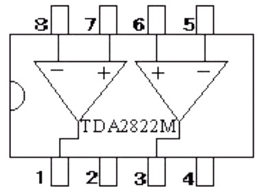
Simple and practical TDA2822M integrated power
TDA2030 is ...

STK465 thick film ...

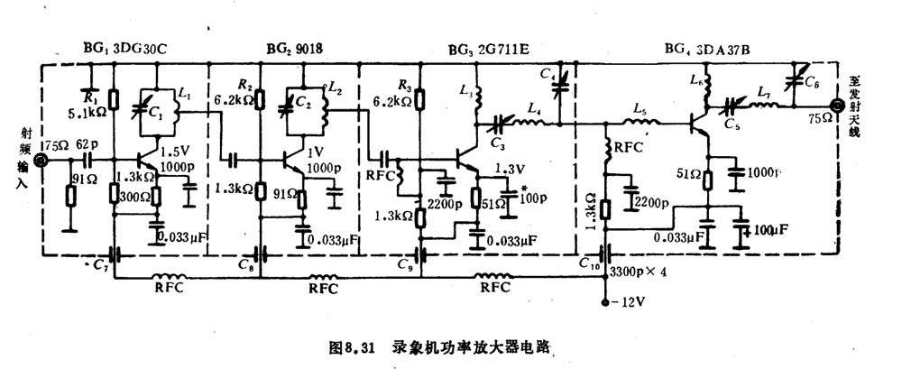
This RF power amplifier can output 2-3 channel signals, covering an area of ​​about one square kilometer, is ...
The inverter introduced here (see Figure 1) is mainly composed of MOS field effect transistors and common power transformers. Its output power depends on MO ...
![[Photo] 15w RF power amplifier](http://i.bosscdn.com/blog/20/06/41/521040781.gif)
![[Photo] Broadband high frequency power amplifier](http://i.bosscdn.com/blog/20/06/41/520536801.jpg)
The cell area we refer to here refers to the radius
Author: Lin Changhao This article describes several mining ...
![[Photo] Using MEC002A to make a remote FM transmitter](http://i.bosscdn.com/blog/20/06/41/5204128230.gif)
Low frequency power amplifier
![[Photo] Practical use of STK3048 and STK6153 ...](http://i.bosscdn.com/blog/20/06/41/5131039354.jpg)
![[Photo] TDA2030 audio power amplifier](http://i.bosscdn.com/blog/20/06/41/5131012891.gif)
Looking at the Hi-Fi amplifiers currently on the market, the output power is 100W ...
![[Photo] Transistor 15W Class A Power Amplifier](http://i.bosscdn.com/blog/20/06/41/513102891.gif)
With the newly launched LM4651 and LM465 from National Semiconductor ...
![[Photo] 125W Class D Subwoofer Power Amplifier](http://i.bosscdn.com/blog/20/06/41/513100868.jpg)
![[Photo] Mark Levinson No. 30 ...](http://i.bosscdn.com/blog/20/06/41/513544752.jpg)
EL34 (6CA7) was first launched by Philips in 1956 ...
![[Photo] 45W transistor tube hybrid power amplifier](http://i.bosscdn.com/blog/20/06/41/513531952.jpg)
This article cleverly combines the electronic tube EL34 and the transistor (op amp), ...
![[Photo] 32W hybrid audio power amplifier](http://i.bosscdn.com/blog/20/06/41/513526493.jpg)
The pre-amplifier adopts a European-made TESLA brand low noise high cheek double transistor ...
![[Photo] Gallstone hybrid power amplifier using switching power supply](http://i.bosscdn.com/blog/20/06/41/513524776.gif)
"Simple" means the circuit of the amplifier is simple, making it easier, as long as the picture ...
![[Photo] Simple fool power amplifier](http://i.bosscdn.com/blog/20/06/41/513432946.jpg)
1. Description: & nb ...
![[Photo] LM386 low voltage audio power amplifier ...](http://i.bosscdn.com/blog/20/06/41/513417261.gif)
The circuit is shown in Figure 5, ...
![[Photo] Using TDA7294 and 2SA1216 / 2S ...](http://i.bosscdn.com/blog/20/06/41/4233420295.gif)
'+ data.data.username +' '; dom + ='
Wireless In Ear Earphone Tws Earbuds /Wireless Earbuds
Product Description
Features:
1, True wireless stereo: realizes movement and wireless control and everyone can share music without wrie
2, Comfortable and convenient: Earplug made of food-grade silica gel material in combinalion with the design to avoid falling off, which makes you comfortable and relieved,also the Earbuds can be Dual or Single use.
Specification
Bluetooth Version: Bluetooth 4.2+EDR
Voice prompt for calling number
Voice prompt for power and or off
Supports :A2DP1.3/HFP1.6/HSP1.2/AVRCP1.6/DI1.3
Adopt the advanced CVC6.0 active noise-cancellation
Built-in superior HD microphone, provide clear and loud sound
Selectable colors: black,,blue and Green
Tws Earbuds,Fully Wireless Earbuds,Wireless In Ear Headphones ,Mini Wireless Earbuds
Shenzhen Greater Industry Co., Ltd. , https://www.szgreater.net