Abstract: An intelligent controller is designed by studying the output characteristics of solar panels, the charge and discharge characteristics of batteries and the driving circuit of high-power LED street lamps. The controller is based on STC single-chip microcomputer, with DC/DC conversion circuit as the hardware foundation, PWM technology as the means to adjust the output voltage and current, and three-stage strategy to realize the charging of the battery. In the fast charging phase, the MPPT algorithm is adopted. The semi-power point strategy controls LED lighting, which greatly highlights the environmental protection and energy saving advantages and application prospects of solar LED street lighting systems.
Faced with the reality that the earth's ecological environment is deteriorating and resources are increasingly scarce, governments around the world have adopted many policies and measures to support and develop energy-saving and environmental protection industries. Solar LED street lamps are a comprehensive application of solar energy development and energy-saving technologies in the field of lighting, and have the dual advantages of environmental protection and energy conservation. According to statistics, lighting consumption accounts for about 20% of the total electricity consumption. Reducing lighting power is an important way to save energy. Solar energy is clean, environmentally friendly and recyclable. LED lighting is the world's most advanced lighting technology. It is the fourth generation light source after incandescent lamps, fluorescent lamps and high-intensity discharge lamps. It has a simple structure, high efficiency and weight. Light, safe performance, no pollution, maintenance-free and long life, strong controllability and other characteristics, is considered to be the best way to achieve energy saving in the lighting field. Statistics show that only LED street lights save energy, saving China about one dam from the Three Gorges Dam every year. It is precisely because of the energy-saving and environmental protection advantages of LED lighting fixtures that in recent years, its global output value has maintained an annual growth rate of more than 20%. China has also launched green lighting projects, semiconductor lighting projects, and the "Ten Cities and Ten Thousand Miles" plan. Advance the development of the industry.
The solar LED street lamp controller designed in this paper firstly detects the solar cell output and battery power and other parameters to determine the system working state, and uses the maximum power point tracking MPPT algorithm to achieve maximum energy collection. After the energy storage is completed, the PWM technology is utilized. Adjusting the brightness of the LED to further save energy, thus achieving automatic control and intelligent energy management of the entire system, and is more conducive to the application of solar street lamps.
1 Introduction to Solar LED Street Light System
1. 1 The composition of the solar LED street light system
The solar street light system consists of the following parts: solar panels, LED lamps (including LED light source, pole and lamp housing), controller, battery pack, as shown in Figure 1.
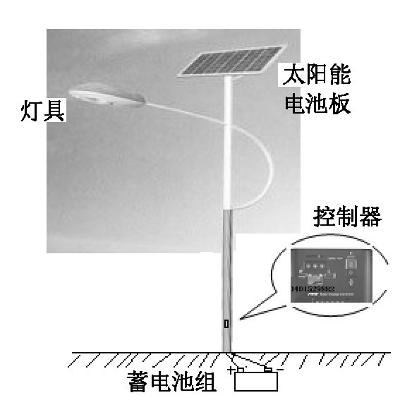
Figure 1 Solar street light system
1. 2 Basic Principles of Solar LED Street Light System
The solar panel made by the photovoltaic effect principle receives solar radiation energy and converts it into electric energy output during the day, and is stored in the battery through the charge and discharge controller; when the illumination is gradually reduced at night, the charge and discharge controller detects this change, and the battery starts. Discharge the LED street light. After the battery is discharged for about 10 hours, the charge and discharge controller operates and the battery discharge ends.
According to the sunshine characteristics of Hainan Sanya and the design standards of urban road lighting, the components of the system are as follows: LED street light 1 group (32 W, 24 V, 1.4 A; LED 1 W light source; 4 groups of parallel, 8 sets in series ; 2 solar panels (each group rated output voltage 18 V, operating current is 5. 6 A, open circuit voltage is 21. 2 V, short-circuit current is 6. 1 A, peak power is 80 W); battery (12 V, 200 Ah; Overcharge voltage 14. 8 V, float voltage 12.3 V, over discharge voltage 10. 8 V).
2 hardware design
Although the solar LED street light controller is the least valuable part of the overall system, it is the core control part of the entire system.
A well-designed controller, in addition to the most basic charge and discharge control functions, can also control the solar cell array to absorb solar energy as much as possible to improve efficiency; prevent battery overcharge and deep discharge, and extend battery life; Environment, adjust the brightness of the LED light source, especially in the middle of the night to achieve half-power lighting load, so as to save energy and so on. Since the output power of the photovoltaic panel has a large uncertainty, the charge and discharge characteristics of the battery are nonlinear, and the two are greatly affected by the environment, designing a good performance charge and discharge controller has a great influence on the system performance. This article is a useful exploration of controller design.
The controller designed in this paper uses STC12C5410AD microcontroller as the main control device. The device has 4 PWM channels, 8 10-bit ADC channels, and the operating frequency is up to 35 MHz. The instruction is compatible with 51 MCU but the speed is 8 ~ 12 times, which is very suitable for this. Design requirements. Since the two sets of solar cells are connected in series, the output voltage is 36 V, the battery voltage is 12 V, and the LED street lamp operates at 24 V. Therefore, the charging circuit uses a DC/DC step-down conversion circuit (Buck), and the discharge circuit uses DC/DC. Boost conversion circuit (Boost), through the software to achieve charge and discharge control strategy, and ultimately achieve the purpose of improving efficiency and energy saving (as shown in Figure 2). This paper focuses on the charge and discharge circuit and its control strategy.
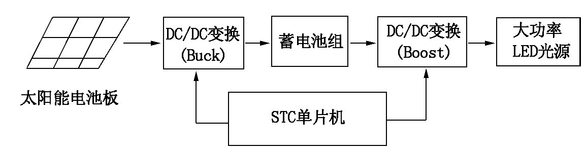
Figure 2 SIC-based solar LED street light control system block diagram
2. 1 charging circuit and control strategy
The charging circuit consists of inductor L1, power MOSFET T1 and freewheeling diode D2 to form a buck Buck circuit, as shown in Figure 3. The output voltage of the solar panel can be changed by changing the pulse width (Pulse Width Modulation, PWM) applied to the MOSFET control gate. By detecting the output voltage and current of the solar panel, the voltage and current of the battery, determining the state of charge of the battery, and selecting an appropriate charging mode to optimize charging of the battery. When the battery voltage exceeds a certain voltage, turn off T1 to prevent the battery from overcharging. When the system detects sufficient ambient light, the controller enters charging mode.
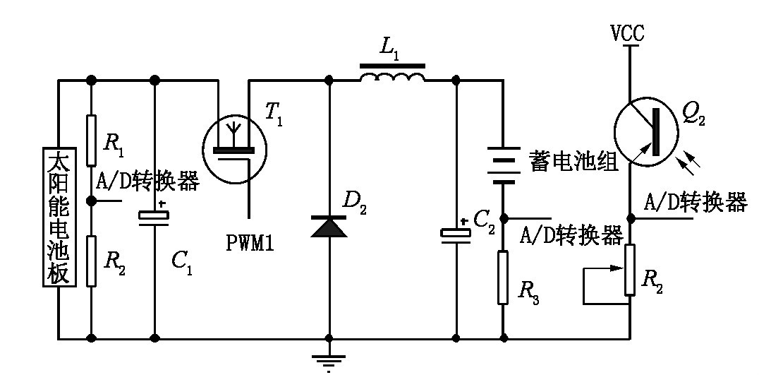
Figure 3 Buck main charging circuit
However, the efficiency of charging is closely related to the characteristics of the charging power source (solar battery), load (battery), and environment. The output power of a solar cell is a nonlinear function of the intensity of the sun and the ambient temperature, as shown in Figure 4.
That is to say, when the sunshine intensity is increased, the maximum output power is correspondingly increased; when the temperature is increased, the output power is decreased; but under certain conditions, there is always a maximum output power point. When the temperature effect is neglected, the intersection of the output characteristics of different illumination conditions and the load curve L, A, B, C, D, E (operating point) is obviously not the maximum power point. If direct matching is used, the output power loss is inevitable. .

Figure 4 Output characteristics of solar photovoltaic cells
Using the maximum power point tracking MPPT (Maximum Power Point Track) control strategy, the collected solar energy can be converted into electrical energy as much as possible and stored in the battery pack. The MPPT control strategies mainly include algorithms such as interference observation method, admittance addition method and fixed parameter method. Here, the interference observation method is adopted. The idea is that the controller changes the output voltage or current of the photovoltaic cell with a small step size in each control cycle---"interference", and the direction of change can be increased or decreased; Output power, if the output power increases, continue the interference process in the direction of the previous cycle; if the output power decreases, change the direction of the interference, and finally reach the stable at the maximum power point, and the step size can be reduced at this time. Further approach the maximum power point.
In addition, the lead-acid battery is a relatively economical and practical power storage device under the current conditions. The capacity and life of a lead-acid battery are important parameters of the battery and are greatly affected by the charging method. The acceptable ideal charging curve is a curve in which the charging current decays exponentially with time, but the polarization phenomenon limits the life of the battery and the charging mode of the photovoltaic cell power generation system. Therefore, according to the battery charging characteristic curve, a phased charging strategy is adopted to improve the charging efficiency and extend the life of the battery. The charging strategy of the battery here is three-stage charging (fast charging, over charging and floating charging).
(1) The output mode of the charging circuit in the fast charge phase is equivalent to the current source. The output current of the current source is determined based on the maximum acceptable current of the battery. During the charging process, the battery terminal voltage is detected. When the battery terminal voltage rises to the switching threshold, the charging circuit shifts to the overcharge phase. The output current is fixed and the output voltage is controlled using the MPPT algorithm.
(2) The overcharge phase charging circuit provides a higher voltage to the battery while detecting the charging current. When the charging current drops below the switching threshold, the battery is considered to be fully charged and the charging circuit is turned to the floating charging phase.
(3) After the battery pack is fully charged in the floating charge phase, the best way to maintain the charge is to provide the battery with a precise, temperature-compensated float voltage.
2. 2 discharge circuit and control strategy
The load of the discharge circuit is a high-power LED street light, which is a green light source connected by high-brightness LEDs of 1 W and above in a certain topology. The luminous intensity of a high-power LED street light is proportional to the current flowing through it. Since the current and voltage parameters of high-power LEDs have typical PN junction volt-ampere characteristics, small changes in forward voltage drop cause large forward current variations. Unstable operating currents can affect LED life and light decay, so high-power LED drivers must provide a constant current. The control circuit mainly adopts DC/DC boost drive circuit (Boost), the control strategy adopts pulse width modulation (PWM), and the Boost charging circuit is shown in Fig. 5.

Figure 5 Boost discharge circuit.
Inductor L2, power MOSFET Q2 and D3 form a step-up DC/DC converter. The output PWM2 is controlled by a single-chip microcomputer to obtain a stable output voltage. The constant current control of the two LEDs is controlled by PWM3 and PWM4 channels. These two loads can also be used as half-power point control; R7 and R10 provide current feedback sampling of the LED illumination driver circuit; other time control functions, temperature compensation circuits and battery over-discharge protection circuits are not discussed in detail here.
3 software design
The software design mainly assists the hardware circuit to complete the control strategy of the controller, which consists of the main program and subroutines such as charging and discharging, as shown in Figure 6 ~ 9. The charging subroutine completes the three-stage charge conversion according to the voltage and current of the battery. The fast charge phase uses the MPPT algorithm to maximize the output power of the photovoltaic cell. The electronic discharge program adjusts the load current through PWM technology, and the load can be completely cut off in the middle of the night to achieve a half-power lighting load.
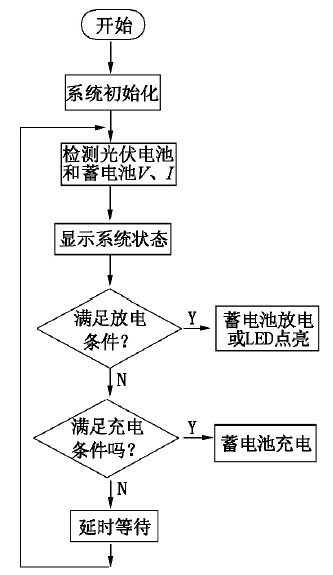
Figure 6 main program flow
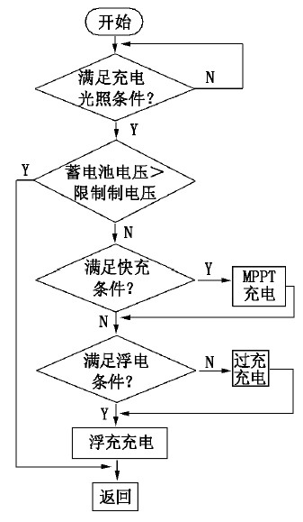
Figure 7 charging subroutine flow

Figure 8: Using the MPPT algorithm to track the maximum power flow during the fast charge phase
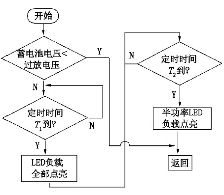
Figure 9 Electronic program flow
4 Conclusion
The solar LED street lighting system is the perfect combination of solar energy development and a new generation of green light source LEDs. After many times of comprehensive debugging of software and hardware, this article uses STC12C5410AD single-chip microcomputer as the core design of the intelligent controller, which realizes the three-stage charging control function as a whole, and can effectively prevent the battery from overcharging; at the same time, it can realize the timing and half-power point to cut off the load. When the battery voltage is lower than the over-discharge voltage, the load will also be cut off, so that the battery is over-discharged. The system has certain practical value in energy utilization and work reliability. Considering the abundant wind resources in Sanya, the next research direction will be to make full use of the complementarity of solar energy and wind energy to ensure uninterrupted light throughout the year. Lights, thus moving towards a truly zero-pollution, zero-emission, green lighting system.
references:
[1]. STC datasheet http://+_2043151.html.
[2]. STC12C5410AD datasheet http://+_1135295.html.
[3]. R10 datasheet http://
Water cooling is a kind of mature graphic card heat dissipation method, the application of liquid-cooling technology to the computer field is not actually due to the air cooling has developed to the end, because the specific heat of the liquid is far greater than the air, generally the liquid cooling radiator has a good effect of heat dissipation, at the same time youcan also get good control of the noise.
Graphics Card / GPU Water Block
Gpu Water Block,Graphics Card Water Block,Graphic Card Water Block,Water Cooling Block
Dongyuan Syscooling Technology Co., Ltd. , https://www.syscooling.com