Based on the X-ray transmission attenuation law, a design scheme of X-ray energy spectrum data acquisition system based on DSP is proposed. This program focuses on the hardware circuit and software design for energy spectrum data acquisition. The hardware circuit is mainly composed of preamplifier, filter, main amplification and peak hold circuit. The software mainly consists of TMS320F2812 pulse signal after preprocessing. Perform multiple pulse amplitude analysis operations and finally plot the X-ray energy spectrum. The debugging results show that the system has the characteristics of simple circuit design, high sampling accuracy and strong anti-interference ability.
0 Preface
X-rays are generated by high-energy electrons in decelerating motion in materials or transitions from orbital electrons in the inner layer of the atom. Therefore, they are highly penetrable and are widely used in radiation detection and medium identification. When the ray energy is constant, the attenuation of the X-ray radiation intensity is only related to the medium through which the X-ray penetrates different media, and the transmission intensity is different. Therefore, related research on media design can be performed by analyzing the detected X-ray intensity.
The detection of X-rays is achieved by the intensity of the radiation after the detector receives the radiation penetrating substance. In this paper, a scintillation detector consisting of NaI (Tl) crystal and photomultiplier tube is used for X-ray detection. The pulse signal amplitude is proportional to the transmitted ray intensity, so the analysis of the pulse signal amplitude provides important information for medium identification. In this paper, the high-speed DSP chip TMS320F2812 is used as the main controller to complete the pulse signal amplitude analysis and processing.
1 system overall frame design
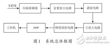
The X-ray intensity detected by the scintillation detector is generally weak. It needs to be pre-processed by amplification, filtering, peak hold, etc., and then use the DSP to perform A/D conversion, pulse amplitude analysis, data storage and upper level processing on the processed signal. The communication between the machines finally draws a line graph about the X-ray intensity. The X-ray energy spectrum data acquisition system is mainly composed of five parts: preamplifier circuit, filter circuit, main amplifier circuit, peak hold circuit and DSP main control circuit. The overall block diagram is shown in Figure 1.
2 Design of each component of the system
2.1 Design of preamplifier circuit
The preamplifier circuit is the key to the design of the entire pre-stage pre-processing circuit. Under unshielded conditions, the transmitted X-rays are generally in the background noise of transformer electromagnetic radiation, power frequency interference, background radiation, etc., from a strong background. Extracting the X-ray intensity carrying the information of the identification medium in the noise requires high performance of the entire X-ray energy spectrum data acquisition system, and the preamplifier circuit is an important component of the front end of the pre-processing circuit, so the system The preamplifier circuit designed is shown in Figure 2. Differential op amps have a high common-mode rejection ratio that rejects errors introduced by various common-mode interferences.
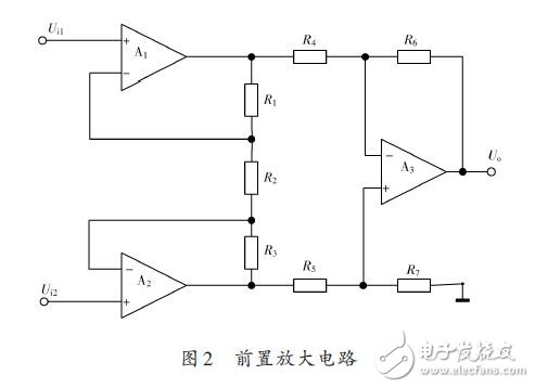
The circuit designed in Figure 2 consists of three basic operational amplifiers, in which the op amps A1 and A2 form a phase-in parallel input to the first stage of amplification to increase the input impedance and gain of the amplifier. A3 is a differential amplifier that acts as the second stage of the amplifier. . The common mode rejection ratio of the entire circuit depends on the degree of symmetry of A1 and A2 in the first stage amplifying circuit. The common mode rejection ratio of the second stage amplifying circuit depends on the closed loop gain of the differential op amp A3 and the matching accuracy of the resistor. From Fig. 2, the output voltage of the preamplifier circuit can be calculated as Uo. When Ui1=Ui2, the current in R2 is zero, so the output voltage Uo=0. It can be seen that the circuit amplifies the differential mode signal and suppresses the common mode signal.
2.2 Filter circuit design
Since the noise and the signal are simultaneously amplified, it is not conducive to the operation of the subsequent amplifying circuit, so the signal needs to be filtered after being amplified by the preamplifying circuit. In order to ensure the accuracy of the X-ray detection, a band-pass filter circuit composed of a voltage-controlled voltage source second-order high-pass filter and a second-order low-pass filter circuit in series is designed as shown in FIG. 3 after the preamplifier circuit.
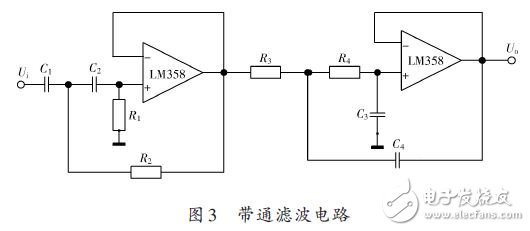
Figure 3 is a designed bandpass filter circuit consisting of active high-pass and active low-pass filter series with a bandwidth ranging from 100 kHz to 1 MHz. High-pass and low-pass filtered op amps are selected for high precision and low accuracy. Bias, low power dual op amp chip LM358. According to the fast design theory of the active filter circuit, the parameters of the high and low pass filter can be obtained.
The high-pass filter has an in-band gain of 1 and a cutoff frequency of 100 kHz. The parameters of the high-pass filter are: C1=C2=800 pF, R1=R2=20 kΩ; the in-band gain of the low-pass filter is 1, cutoff The frequency is 1 MHz and the parameters of the low-pass filter are: C3=C4=1 nF, R3=R4=160 Ω.
If you are new to the concept of using an electric kettle, you might be overwhelmed by the variety of electric kettles that are displayed on the store shelves and have difficulty deciding which one would be the best to suit your individual needs or desires. This introduction will give you some basic information about some of the features that are available on various types of electric kettles so that you can make a more informed decision when choosing one for use in your home.
Features:
Spend few minutes to boil : After 5 minutes, hot water will finish for you to drink.
3 protection functions : The on/off button is on the handle, making it easy to turn the kettle off when you pick it up. A concealed heating unit reduces the amount of buildup in the kettle.
It will be a problem when you forget to close the button.Once the water boils the kettle shuts itself off.Do not have to worry about damaging it by letting it run dry. When water runs dry,It will cut the electric by itself.
Multiple Cups: Water can be loaded to 1.8Liter.
Materials :
Food grade stainless steel, more healthy and hygienic. PP handle wieh heat insulation material provides scald resistance. Durable controller performance with 360 degree rotation cordless base design.
OEM & ODM service : Try best to support you during production and provide better after-sales service.Enhance your brand popularity.
Application:
Make a cup of tea.
Boil eggs.
Cook noodles.
Electric Water Kettle
Electric Water Kettle,Aluminium Electric Water Kettle,Mini Electric Water Kettle,Stainless Steel Electric Water Kettle
Guangzhou Taipeng Electrical Appliances Technology CO., LTD. , https://www.kettles.pl