Introduction
Today MEMS microphones are gradually replacing electret condenser microphones (ECMs) in audio circuits. The two microphones, ECM and MEMS, have the same function, but the connection between each and the rest of the system is different. This application note will introduce these differences and provide design details based on a simple MEMS microphone-based replacement circuit.
ECM connection of the audio circuit
The ECM has two signal leads: output and ground. The microphone is biased by a dc bias on the output pin. This bias is typically provided by a bias resistor and the signal between the microphone output and the preamplifier input is AC coupled.
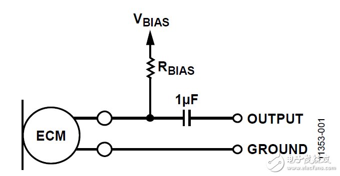
Figure 1. ECM circuit connection
A common use case for ECM is to use it as an inline voice microphone in headphones that are connected to the phone. In this case, the connector between the headset and the phone has four pins: the left audio output, the right audio output, the microphone signal, and the ground. In this design, the output signal of the ECM and the DC bias voltage are transmitted in the same signal line. The bias voltage source is typically approximately 2.2 V.
MEMS microphone difference
The input bias voltage is not used on the signal pins of the analog MEMS microphone. However, it is a three-terminal device with different pins for power, ground, and output. The supply voltage to the VDD pin is typically 1.8 to 3.3 V. The signal output of the MEMS microphone is biased by a DC voltage, typically equal to or close to 0.8 V. In the design, the output signal is usually AC coupled.
A key advantage of using a MEMS microphone over ECM is its power supply rejection (PSR) performance. MEMS microphones typically have a PSR of at least 70 dBV, but ECM has no power supply rejection at all because the bias voltage is directly connected to the microphone through a resistor.
Circuit changes required to replace ECM with MEMS microphones
For systems originally designed around ECM, the fundamental challenge in switching to MEMS microphones is that there is no separate signal for the power and microphone outputs, such as when using a headset microphone. If you make small changes to your circuit, you can use MEMS microphones in such designs. First, the downstream signal provided by the DC bias in the signal chain must be isolated from the output signal of the microphone. Second, this DC bias must be used to power the MEMS microphone and not allow the microphone's output signal to interfere with the power supply. DC bias isolation can be achieved with an ac coupling capacitor, and the MEMS microphone's power supply can be provided through a carefully designed circuit that acts as a voltage divider and low pass filter. The ADMP504 MEMS microphone is used as an example in the following design. A 2.2 k bias resistor is used.

Figure 2. MEMS microphone with one wire for power and output signals
Figure 2 shows a design example that implements the above functions. In the design of the earphone, the circuit portion on the left side of the earphone connector will be in the actual earphone, and the 2.2 k bias resistor and the 1 F AC coupling capacitor are in the source device (such as a smart phone). Resistors R1 and R are biased to form a voltage divider, and the MEMS microphone reduces the V bias voltage to the supply voltage of the VDD pin. Depending on the V bias, R bias, and the value of the desired VDD voltage, resistor R1 may need to be very small, as shown in the following example. To calculate the required series resistance (R offset + R1), the microphone can be modeled as a resistor that will have a fixed current flowing through it. The typical supply current for the ADMP504 is 180 A at VDD = 1.8 V. According to Ohm's law, when the voltage on VDD is 1.8 V, the microphone can be modeled as a 10 kΩ resistor. To solve the appropriate resistor R1 value, the voltage divider formula used is:
[Microphone VDD] = [Bias Voltage] &TImes; (10 k / (10 k + R1 + R Offset))
According to this formula, a 2.2 k R bias resistor and a 499 R1 resistor will separate 1.73 V from the 2.2 V bias voltage to the VDD of the microphone. When selecting the R1 value, trade-offs need to be made; as shown below, this value is too large, which will cause VDD to be too small, but in order to prevent C2 from being too large, this value cannot be made too small.
Solar LED land lamp uses sunlight as the energy source, charges during the day and uses at night, does not need complex and expensive pipeline laying, can arbitrarily adjust the layout of lamps and lanterns, safe and energy-saving, pollution-free, stable and reliable without manual operation, saving electricity and maintenance. Solar LED street lamp is mainly composed of solar cell module (including bracket), LED lamp holder, control box (with controller, battery) and lamp pole.
Solar Led Street Light,Street Light Lamp,Solar Powered Street Lights,Solar Powered Led Street Lights
Yangzhou Heli Photoelectric Co., Ltd. , https://www.heli-eee.com