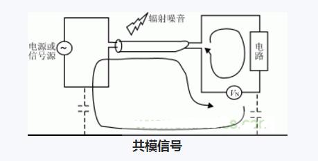
**Definition of Common Mode Signal**
A common mode signal refers to a signal that appears simultaneously and identically on both the in-phase and the inverting inputs of a differential amplifier or an instrumentation amplifier. This type of signal is often caused by external interference, such as noise from power lines or electromagnetic fields. For instance, it can be a balanced pair of noise voltages introduced into both ends of a differential line, or a DC voltage present due to a ground potential difference between the signal source and the receiving end. In an ideal differential amplifier, the common-mode signal should be completely canceled out because the two inputs are designed to subtract identical signals. The ability of a differential amplifier to reject such signals is measured by the Common Mode Rejection Ratio (CMRR).
The pure form of a common mode signal is defined as:
V1 = V2 = VCOM (3)
with equal magnitude and 0° phase difference.
Additionally, V3 = 0 (4).
**Characteristics of Common Mode Signals**
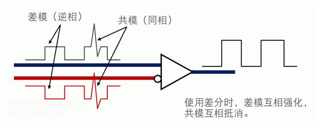
Common mode components have the same amplitude and phase. They are typically unwanted and can interfere with the desired differential signal.
**Why Suppress Common Mode Signals?**
Any signal can be decomposed into a common mode component and a differential mode component. The common mode signal is the same on both inputs, while the differential mode is the difference between them. If not suppressed, the common mode signal can be amplified along with the desired signal, leading to distortion or inaccuracies. For example, if the input signals are A and B, then:
A = m + n
B = m - n
Here, m represents the common mode component, and n is the differential mode. To improve signal integrity, it's crucial to suppress the common mode signal.
A key parameter used to measure this capability is the Common Mode Rejection Ratio (CMRR), which is the ratio of the differential gain to the common-mode gain. A higher CMRR means better rejection of unwanted common-mode signals.
**Suppression of Common Mode Signals**
To suppress common mode signals, specialized circuits are used. These circuits typically include windings placed on both conductors to create opposing magnetic fields that cancel out the common mode current. A third winding may also be used to induce an inverted signal that further cancels the original common mode disturbance. The placement of these windings is critical, as they must be positioned to effectively counteract the noise without affecting the differential signal.
**Understanding Common Mode Choke Coils**
Common mode choke coils are widely used in electronic systems to suppress unwanted common mode noise. They work by creating high impedance for common mode signals while allowing differential mode signals to pass through with minimal loss. However, their performance varies with frequency.
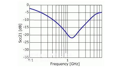
The characteristics of a common mode choke coil are often described using S-parameters, specifically the differential mode insertion loss (Sdd21) and the common mode insertion loss (Scc21).
As shown in Figure 4, the differential mode insertion loss increases with frequency, meaning higher frequency differential signals experience more attenuation. In contrast, the common mode insertion loss (Figure 5) has a peak at certain frequencies, indicating the most effective suppression occurs at those points.
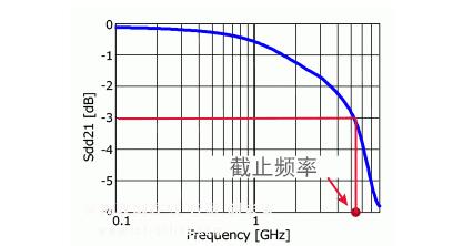
The cutoff frequency of a common mode choke coil is usually set at three times the frequency of the differential signal. This ensures that the choke coil provides sufficient suppression at the relevant frequencies. However, the exact cutoff frequency may vary depending on the application and interface requirements.
In practice, even if the signal frequency is below three times the specification, the waveform may still remain intact. The final judgment on signal quality is often based on industry standards.
Since noise characteristics differ across devices, the optimal frequency range for common mode suppression can vary. For example, if a specific noise frequency exceeds radiation limits, selecting a choke coil that targets that frequency range can significantly improve signal integrity.
UCOAX offers LVDS Assemblies service for oversea customer.
Lvds Cable Assembly,Lvds Cables,Lvds Cable Extension,Lvds Cable Assembly Function
UCOAX , https://www.ucoax.com