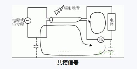
**Definition of Common Mode Signal**
A common mode signal is a signal that appears simultaneously and in phase on both the non-inverting and inverting inputs of a differential amplifier or an instrumentation amplifier. This type of signal is typically unwanted and can be caused by external interference, such as noise from power lines or ground potential differences. For example, if two balanced wires are subjected to the same noise voltage, this would be considered a common mode signal. Similarly, a DC voltage present on both sides of a balanced line due to a difference in ground potentials can also act as a common mode signal.
In an ideal differential amplifier, the common mode signal is completely canceled out because the amplifier only responds to the difference between the two input signals. The ability of a differential amplifier to reject common mode signals is measured by the Common Mode Rejection Ratio (CMRR). A higher CMRR means better rejection of unwanted common mode signals.
The pure common mode signal can be mathematically represented as:
V1 = V2 = VCOM (3)
This indicates that both input signals have the same magnitude and phase, while the differential component (V3) is zero:
V3 = 0 (4)
**Characteristics of Common Mode Signals**
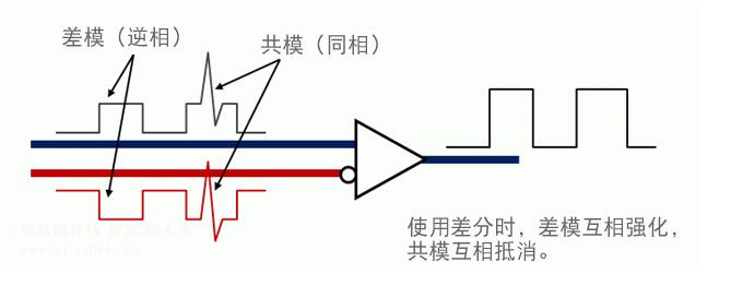
Common mode signals have equal amplitude and the same phase. They are often introduced through conductive paths or electromagnetic coupling and are generally considered noise in differential systems.
**Why Suppress Common Mode Signals?**
Any pair of signals can be decomposed into a common mode component and a differential mode component. The common mode signal is the same on both inputs, while the differential mode signal is the difference between them. If not properly suppressed, the common mode signal can interfere with the desired differential signal, especially when the system amplifies the differential signal.
For example, if the two input signals are A and B:
A = m + n
B = m - n
Then, m represents the common mode signal, and n represents the differential mode signal. Here, m = (A + B)/2 and n = (A - B)/2.
To measure how well a differential amplifier rejects common mode signals, we use the Common Mode Rejection Ratio (CMRR), which is the ratio of the differential gain to the common mode gain. A higher CMRR indicates better performance.
**Suppression of Common Mode Signals**
To suppress common mode signals, specialized circuits such as common mode chokes or baluns are used. These circuits are designed to block or reduce the common mode components while allowing the differential signal to pass through. One method involves using windings on a magnetic core to create opposing magnetic fields that cancel out the common mode current.
Another approach involves detecting the common mode signal and injecting an inverted version back into the circuit to cancel it out. This technique is often used in high-speed data transmission systems to improve signal integrity and reduce electromagnetic interference (EMI).
**Understanding Common Mode Choke Coils**
Common mode choke coils are widely used in electronic circuits to suppress unwanted common mode noise. These components work by creating a high impedance path for common mode currents while allowing differential mode signals to pass with minimal loss.
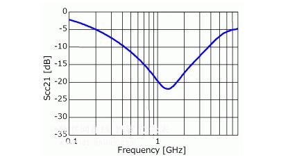
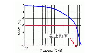
The performance of a common mode choke is characterized by its frequency response, particularly the differential mode insertion loss (Sdd21) and the common mode insertion loss (Scc21). These parameters show how effectively the choke coil attenuates different types of signals at various frequencies.
As shown in Figure 4, the differential mode insertion loss increases with frequency, meaning that higher frequency differential signals experience more attenuation. In contrast, the common mode insertion loss (Figure 5) shows a peak at certain frequencies, indicating where the choke coil is most effective at suppressing common mode noise.
**Key Considerations**
- The cutoff frequency of a common mode choke is typically set to three times the frequency of the differential signal to ensure effective noise suppression.
- However, actual performance depends on the specific application and interface standards.
- Since noise characteristics vary between devices, the optimal common mode insertion loss may differ depending on the system.
By carefully selecting and designing common mode suppression techniques, engineers can significantly improve signal quality and system reliability in a wide range of applications.
AUDIO RETURN CHANNEL (ARC) and Ethernet. Best cable for gaming with features like Variable Refresh Rate (VRR), Quick Media Switching (QMS), Quick Frame Transport (QFT)
UCOAX Custom Made HDMI 2.1 Cable with different connectors and length.
SUPPORTS THE LATEST 8K resolution at 60Hz. 4K supports at 120Hz. Max resolution up to 7680x4320. Supports 144Hz monitors.
HDR HIGH DYNAMIC RANGE for the best details and color depth. Wider range of colors, brighter whites, and deeper blacks.
HDMI 2.1 Cable for XBOX SERIES X, PLAYSTATION 5, 8K/4K BLU-RAY PLAYERS, Apple TV, PS4, XBox One X, XBox One S, Roku Ultra, High End Gaming PC's and other HDMI-enabled devices to 4K & 8K TVs, Monitors & Projectors.
AUDIO RETURN CHANNEL (ARC) and Ethernet. Best cable for gaming with features like Variable Refresh Rate (VRR), Quick Media Switching (QMS), Quick Frame Transport (QFT)
Hdmi 2.1 Cable,8K Hdmi Cable,Hdmi 2.1 Certified Cable,Best Hdmi 2.1 Cable
UCOAX , https://www.ucoax.com