1 Introduction
This article refers to the address: http://
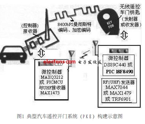
This paper will introduce the new design and application development of the car wireless remote control door opening system. A typical wireless remote door opening system - the remote key (RKE) system used in automotive safety applications, is shown in Figure 1. The system consists of a controller (or receiver) mounted on the car and a transceiver (or transmitter) carried by the user, ie a wireless remote control door key. The transceiver typically includes a microcontroller, RF device, and human interface devices such as buttons and LEDs. The microcontroller can be used with the DS89C440 or PIC16F639, and the RF device can be used with the MAX7044 or MAX1479 or TRF6901. The transceiver is normally turned off and only works when a button is pressed or when data needs to be sent. The transceiver is used to send data to the controller and is therefore one-way communication. However, this situation is changing. The new smart transceiver can send data as well as receive data, so it is two-way communication. In a two-way communication system, the controller (mounted on the car) and the transceiver (ie the car key) enable automatic communication without the need for a human-machine interface.
   2 design ideas
It can be seen from the above-mentioned wireless remote control door opening system that the design concept of the system solution is based on constructing a transmitter (remote key) and a receiver with a microcontroller.
The MAXQ family is known to be a 16-bit RISC microcontroller optimized for low-noise design and optimized for analog circuit operation, and can be integrated with RF receiver devices to create the best solution for analog circuits.
   2.1 Remote control key (transmitter or transceiver) and receiver (on-board controller)
The remote control key can be configured with the DS89C450-KIT and MAX7044 or two evaluation boards (EV KIT), the DS89C450-KIT and the MAX7044EVKIT (EVht). It can be mounted in a housing with the rechargeable battery located below. If an antenna is used, the transmission distance is several orders of magnitude beyond the standard keychain.
The receiver (on-board controller) consists of a MAXQ3212 16-bit microcontroller and a MAXl473 receiver mounted side-by-side. The connection is connected to the car's body control module (BCM). For debugging or demonstration, a dedicated MAXQ3212 port pin can be used to send asynchronous serial data at 9600 bps.
The reason why the MAXQ3212 16-bit microcontroller is used here is because the MAXQ series is a 16-bit RISC microcontroller optimized for low-noise design and optimized for analog circuit operation. In addition to digital components, it also integrates high-precision simulation. The function, thus the application requires fewer chips, can be integrated with the RF receiver device MAXl473 to build the best solution for the analog circuit, and does not interfere with the RF signal. Its superior power consumption and powerful combination of features make product design and build easier and reduce time-to-market.
The RF receiver device MAXl473 is the latest 300MHz to 450MHz ASK (Amplitude Modulated Modulation) RF receiver with an average sensitivity of -114dBm, which consumes only 5.5mA (typ) of normal operation. Built-in image rejection, eliminating the need for a front-end SAW filter. In sleep mode, the MAXl473 can start and send data in less than 250ps, ensuring a deeper sleep cycle and longer battery life. The MAXl473 operates from a 3V to 5V supply voltage. The 300MHz to 450MHz transmitter and receiver have the greatest advantage of doubling the effective range of the RKE system, ideal for sub-battery-powered devices including key, car alarm and tire pressure detection.
   2.2 About analog signal strength measurement
The MAXl473 receiver provides an analog received signal strength indicator (RSS1) that can be measured. The MAXQ3212 includes an analog comparator to compare the VREF and CMPI inputs and generate a pulse width modulated signal (PWM) on the timer output pin. Figure 2 shows the method of constructing an ADC from a comparator and PWM. Send the RSSI signal to the VREF pin of the MAXQ3212 comparator. The timer is then programmed to PWM mode. If the PWM is properly filtered, the DAC output is generated to the T2PB pin and the output (ie, DAC) is connected to the other input CMPI pin of the comparator. The comparator then compares the signal levels and if the signals match, the analog to digital conversion can be successfully performed without a dedicated hardware ADC.
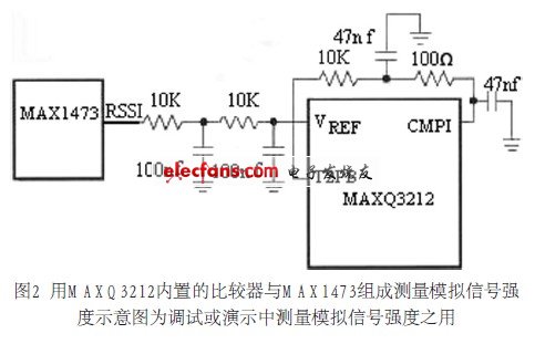
The software does not use the successive approximation method, but uses a slope ADC. Starting from a reasonable minimum, the DAC output slowly increases until the comparator indicates a match.
  2.3 How to decode RF signals
The MAXl473 receiver provides a digital signal output (DATAOUT). Since RF noise is always present, the pin will continuously transition state regardless of whether the keychain is actually transmitting data. To distinguish this noise from the signal, the MAXQ microcontroller must use a small software state machine to measure the time between the rising and falling edge signals to identify the preamble.
The most efficient way to measure the edge interval is to use the interrupt trigger technique. MAXQ can be programmed to trigger an interrupt on either a rising or falling edge. Set the interrupt to the "rising edge" trigger, which starts the measurement. Once a rising edge is detected, the timer is reset and restarted, and the interrupt trigger edge is set to the "falling" edge. The interrupt handler reads the value of the timer on the falling edge. This can be done with a short program to show a code segment that reads and resets the timer and then converts the polarity of the interrupt trigger signal. If the edge interval matches the 8400 bps data rate (plus/minus a reasonable tolerance) and the number of sync pulses specified by the protocol is detected, the microcontroller software state machine switches to receive mode and begins parsing the remaining packets.
2.4 About data flow - the use of Manchester coding
The protocol of the transmitter (remote key) data stream (burst) shown in Figure 1 varies greatly depending on the manufacturer, model, and factory time. For this aftermarket project, using a programmable microcontroller is just right. The 8400bps Manchester-encoded digital data stream is randomly selected and transmitted at 433MHz using ASK (Amplitude Transform Modulation). To use FSK (Frequency Modulation Modulation) or a different transmit frequency, the MAXl473 must be replaced with a different receiver chip.
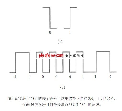
(1) The basic concept of Manchester coding
Each data bit is represented by at least one signal transition, thereby enabling self-synchronization of the data stream. Figure 3(a) shows the representation of 0 and 1, where the falling edge is chosen to be 0 and the rising edge is 1. String data is usually sent first in the LSB. As shown in Fig. 3(b), the ASCII character "A" (41h, 0100.000 lb) is transmitted in the form of 1000.0010b. The coding can be formed by connecting the symbols of 0 and 1. Figure 3(b) forms the encoding of ASCII "A" by connecting the symbols of 0 and 1.
(2) Data flow and software
When the button on the key fob is pressed, the preamble will be sent, followed by the ID, count value and key data, as shown in Figure 4. The transmitter repeats the sequence until the button is released, and a software debouncer is required. In this example code, this is done simply by briefly closing the receiver.
The actual system will also encrypt some of the data to prevent theft of the vehicle. It is generally decrypted by the vehicle body control module (BCM). The receiver software measures the received signal strength, waits and synchronizes to the preamble, decodes the data stream, and transmits the data over the serial port. 2.5 Transmitter (remote control key) and selection of several chips in the receiver
(1) Selection of MAXl473 receiver and MAX7044 transmitter
The RF receiver device MAXl473 is the latest 300MHz to 450MHz ASK RF receiver with the same characteristics as described above.
The MAX7044 device in the transmitter is a transmitter that can output +3dBmASK signal. It is packaged in a tiny 8-pin SOT package. When the duty cycle is 50%, such as Manchester code, it only consumes 7.7mA. The MAX7044 can be powered from a single lithium battery with voltages as low as 2.1V.
The biggest advantage of the 300MHz to 450MHz transmitter and receiver is that it can double the effective distance of the RKE system (that is, the control range is more than twice). It is ideal for battery-powered equipment, including key, car alarm and tire pressure detection.
(2) MAX1471 structural block and application for two-channel receiver to capture two signals simultaneously
Using the MAXl471 dual-channel receiver to capture both signals simultaneously, the ASK and FSK can be received simultaneously, with zero switching time between modes. For low-cost system designs that require both ASK and FSK decoding, the MAXl471 dual-mode receiver can also be self-pollined, allowing the device to maintain a sleep mode of up to 8 minutes and wake up the microprocessor for further energy savings. The MAXl47l operates from 300MHz to 450MHz and includes a built-in 42dB (megascale) image rejection mixer, eliminating the need for a common SAW filter. The MAXl471 has a built-in voltage regulator for 3.3V or 5V that operates down to 2.4V. Figure 5 shows the structure and application of the MAX1471. The MAX1471 can also be used in receivers in automotive tire pressure monitoring systems.
3 intelligent wireless remote control door opening system
A low cost two-way communication transceiver can be implemented with two frequencies, 125 kHz for receiving data and UHF (315, 433 868 or 915 MHz) for transmitting data. Since the propagation capability of the 125 kHz signal is not strong, the range of two-way communication is usually less than three meters.
In such a smart wireless remote-controlled door open system, the controller (receiver) transmits commands using a frequency of 125 kHz while continuously searching for UHF frequency signals from transceivers in the effective range (where the transmitter is said to be more accurate). The smart transceiver is typically in receive mode, waiting for a valid 125 kHz controller command. If a valid controller command is received, the transceiver will respond with a UHF frequency. This is what is commonly referred to as the new passive remote door opener (PKE) system.
The biggest difference between the transmitter in a conventional remote door opening system and the transceiver in a new passive remote door opening system is that the latter has a 125 kHz circuit for two-way communication. A low-cost wireless remote-controlled door open system (PKE) transceiver can be implemented using an integrated system-on-a-chip (SoC) intelligent MCU that includes digital and low-frequency front-end circuits. Figure 6 is a schematic diagram of a smart wireless remote control door opening system.

Since the operation of the intelligent wireless remote control door opening system transceiver relies on automatic communication with the controller, no human-machine interface is required, so the reliability of the system operation directly depends on the signal condition between the controller and the transceiver.
The button on the transceiver of the smart wireless remote control door opening system shown in Figure 6 is used for optional operation, but the action of opening the door can be completed automatically without manual interference. The two-way communication sequence for intelligent wireless remote door opening system applications is as follows: the controller transmits commands using a 125 kHz frequency; the transceiver receives 125 kHz controller commands using three orthogonally arranged 125 kHz resonant antennas; if the commands are correct, the transceiver transmits through a UHF transmitter Response (encrypted data); the controller receives the response data and activates the switch to open the door if the data is correct.
The low frequency antenna of the transceiver (eg 125 kHz) uses an LC resonant circuit. The LC resonant circuit induces a voltage when an electromagnetic wave magnetic field emitted by the controller antenna passes through the coil antenna of the transceiver. In the case where the physical limit of the LC resonant circuit is given, the input receiving voltage of the transceiver is tuned to the carrier frequency (125 kHz) of the controller command by the LC circuit, or the input and receive are received when the antenna coil (inductor L) is facing the controller antenna. The voltage reaches its maximum.
The intelligent MCU in the transceiver includes both a low frequency (LF) front end and a digital portion. The LF front end section constantly looks for input signals. At the same time, the digital circuitry is in sleep mode to reduce battery drain. The digital circuit portion is only woken up when the correct controller command is received (similar to the wake-up MCU pin function in the MAX1471 box in Figure 5). This can be done by using a special wake-up filter in the front end of the LF. The output is generated by programming the LF detection circuit such that only the input signal has a pre-set header flag.
   4 Intelligent wireless remote control door opening system transceiver and its application
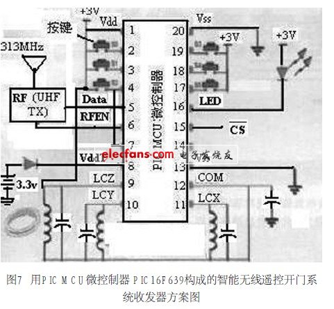
(1) A smart wireless remote-controlled door open system transceiver using a microcontroller PIC16F639 MCU.
Figure 7 shows the scheme diagram. The transceiver uses three orthogonally placed antennas LCX, LCY, LCZ to detect input signals from the X, Y and Z directions. Thanks to its versatile intelligence and its low cost, smart transceivers can be used in a variety of applications, especially in the automotive and security industries. An example of a passive remote door open (PKE) transceiver configuration using a smart MCU, the transceiver uses three orthogonally placed antennas to detect input signals from the X, Y, and Z directions.
(2) Automotive industry: intelligent passive remote control door opening system; remote garage door lock and door opening system; engine start control and tire pressure monitoring system (shown in Figure 5) LF start sensor.
(3) Security industry: long-distance access control; parking space control; automatic door switch.
Smart wireless car communication can be achieved using a two-way communication method. A low-cost two-way communication transceiver can be implemented using an integrated system-on-chip (SoC) intelligent microcontroller (MCU). Battery-free operation can also be achieved by adding a simple voltage charging circuit to the transceiver and generating a DC voltage using the input low frequency controller command.
   5 Conclusion
Evolving wireless communication technologies can integrate independent subsystems in a car. It should be said that the development prospect of wireless remote door opening system based on the use of a microcontroller is promising.
1.ANTENK Flexible Printed Circuit (FPC) and Flexible Flat Cable (FFC) connectors are ZIF (zero insertion force) and LIF (low insertion force) connectors designed to provide a fast, easy, reliable method to make a connection of flexible printed circuits to a PCB. Adam Tech`s special contact design completely preserves conductor integrity by eliminating all wiping action while making connection. Flex circuitry enters the connector and the connector cap is pressed down to capture the flex circuit producing a stable, high pressure connection. Raising the cap releases the pressure for exchange or replacement of circuitry. This series includes single and dual row versions in thru-hole or SMT mounting in vertical or horizontal orientations.
2.Our products are widely used in electronic equipments,such as monitors ,electronic instruments,computer motherboards,program-controlled switchboards,LED,digital cameras,MP4 players,a variety of removable storage disks,cordless telephones,walkie-talkies,mobile phones,digital home appliances and electronic toys,high-speed train,aviation,communication station,Military and so on


FFC Connector Range Available as:
0.3,0.5, 0.8, 1.0,1.25, 2.54mm connector pitch
Surface mount
Side and Top entry
Side entry parts - Top and bottom contact options
ZIF (Zero Insertion Force)
Slide and flip lock actuator styles
Specifications:
Material And Finish:
Insulator: LCP
Lock: PPS
Insert Spring:Phosphor Bronze,
Matte Tin Plated
Solder Platten Area:Phosphor
Bronze,Matte Tin Plated
Voltage:500 V AC(rms)/DC
Current:0.5 A AC(rms)/DC
Contact Resistance:20 mΩ max(initial)
Insulation Resistance:800 MΩ min
Operating Temp:-20°-85°
Fpc Connector,Fpc Cable Connectors,Ffc Cable Connectors,Pitch Fpc Connector,Surface mount FPC/FFC Connectors,Top entry FFC Connectors, Side entry FFC Connectors
ShenZhen Antenk Electronics Co,Ltd , https://www.antenk.com