With the continuous advancement of the social economy and the rapid development of high technology, in daily work and life, cars have become the ideal means of transportation for people. While the car brings convenience to people, it also causes frequent traffic accidents, which causes casualties and loss of economic property. Therefore, the safety of car driving has become the focus of attention. The collision safety technology of automobiles is the most difficult and core part of automobile safety technology. The analysis of highway traffic accidents shows that more than 80% of accidents are caused by driver's reaction, and more than 65% of vehicles collide with each other. The rest belong to the side collision. In order to reduce the occurrence of car accidents, provide a sense of security for users who own cars, develop a simple and reliable, use, enable automatic detection of distance, and find a safety system that alerts the driver when the vehicle is less than a safe distance from the obstacle. Practical significance. Because the ultrasonic detection has the advantages of fast accuracy, the design uses the ultrasonic detection chip to realize the collision warning function.
This article refers to the address: http://
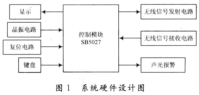
1 Car anti-collision alarm hardware design According to the product cost performance and actual needs, the intelligent ultrasonic ranging IC chip SB5027 developed by Zhongyi Electric Measurement Research Institute is adopted. It adopts CMOS manufacturing process, with on-chip comparator and standard 40 kHz ultrasonic wave. The generator and the echo response pulse receiver are provided with dynamic digital display information output, operation keyboard, data storage, parameter setting and the like. When using SB5027 as distance detection, it has the following characteristics: dynamic digital tracking display; parameters such as upper limit, middle limit and lower limit can be set; alarm setting parameters such as distance, time and timing can be set; maximum range and minimum resolution The rate is set by the user; support value-added ranging function. The system hardware structure design is shown in Figure 1. The system consists of an ultrasonic transmitting circuit, an ultrasonic receiving circuit, a keyboard display circuit, a core function chip, an auxiliary circuit (a reset circuit and a crystal oscillator circuit), and an alarm circuit.
1.1 Ultrasonic Ranging Principle The basic principle of ultrasonic ranging is basically the same as that of sonar echo localization. The ultrasonic generator continuously emits ultrasonic waves of 40 kHz, and when the obstacles are reflected back to the reflected waves, the ultrasonic receiver receives the reflected wave signals and converts them into electrical signals. The time difference T between the transmitted transmitted wave and the received reflected wave is measured, and the distance can be found:
S=(1/2)CT
Where: C is the ultrasonic sound speed, and:
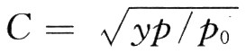
Where: y is the adiabatic volume coefficient of the gas (air is 1.4); p is the gas pressure (sea level is 1.013 × 10⁶ Pa); 钆 is the density of the gas (air is 1.29 kg / m3).
For 1 L of air, the mass is m, the volume is v, and the density is p=m/v.
Therefore:
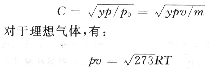
Where: R is the molar gas constant; T is the absolute temperature.
Since y, R, and m are all known constants, the speed of sound C is only related to temperature. If the temperature T is constant, the speed of the sound in the air is independent of the air pressure. C0 = 331.45 m/s at 0 °C. For any temperature, there are: 
1.2 Sound and light alarm, wireless signal transmission and receiving circuit design Automotive anti-collision alarm detection, using ultrasonic sensors. The ultrasonic sensor is composed of an ultrasonic transmitting circuit and an ultrasonic receiving circuit. The ultrasonic transmitting circuit is composed of a Schmitt trigger, a transformer, and a transmitting sensor T probe. Since the SB5027 has a standard 40 kHz ultrasonic generator inside, it directly directs its internal signal (extracted by the pin SONICOUT), but the signal is weak, and the signal must be amplified in the transmitting circuit. The signal is connected in series through two Schmitt reverse flip-flops, and the NPN transistor VT is turned on by the voltage dividing resistor, and the voltage pulse signal at the output end is fed back to the transformer, and the voltage signal is increased by the step-up transformer. To drive the transmitting T40 sensor to emit 40 kHz ultrasonic waves, the circuit diagram is shown in Figure 2.

Ultrasonic signal reception processing is one of the key technologies of the ranging system. Since the ultrasonic receiving circuit amplifies the weak signal outputted by the probe enough to drive and control the latter circuit, the receiving circuit mainly solves the phenomenon of diffuse reflection on the surface of the received signal, so the receiving circuit mainly solves the stability of the received signal, that is, the received signal. Automatic gain control problem. Since the part of the surface where the emitted signal contacts the object is relatively weak, and the distance of the measured distance causes the amplitude of the reflected signal to be uneven. In order to eliminate the effects of the above defects, the receiving circuit should have signal amplification and automatic gain control. In the design, the chip LM331 is used to complete the voltage/frequency replacement. The ultrasonic receiver R filters the received reflected wave through the capacitor and the resistor, converts it into a voltage through the LM331, and then serializes the voltage of the LM331 by two reverse Schmitt triggers and sends it to the ECHO of the SB5027. On the IN side, the circuit diagram is shown in Figure 3.

When the ranging circuit exceeds the limit, the BELLOUT terminal of SB5027 outputs a high level to turn on the transistor VT1, and the alarm is turned on and an alarm sounds. The circuit diagram is shown in Figure 4.
2 software system design Alarm software design flow chart shown in Figure 5. |
After the system is powered on, the main program completes the initialization work, including the initial value of the memory. When the car is in working condition, the alarm device placed in front of and behind the car will collect the on-site signal and transmit it to the SB5027 microcontroller. The signal received by the MCU is processed, calculated and compared. When normal, the alarm does not alarm; if the limit is compared with the lower limit, an audible and visual alarm signal is generated to remind the driver to take corresponding measures.
|
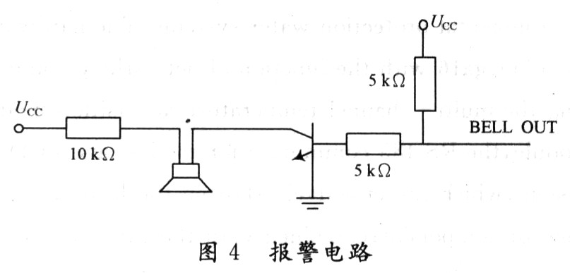
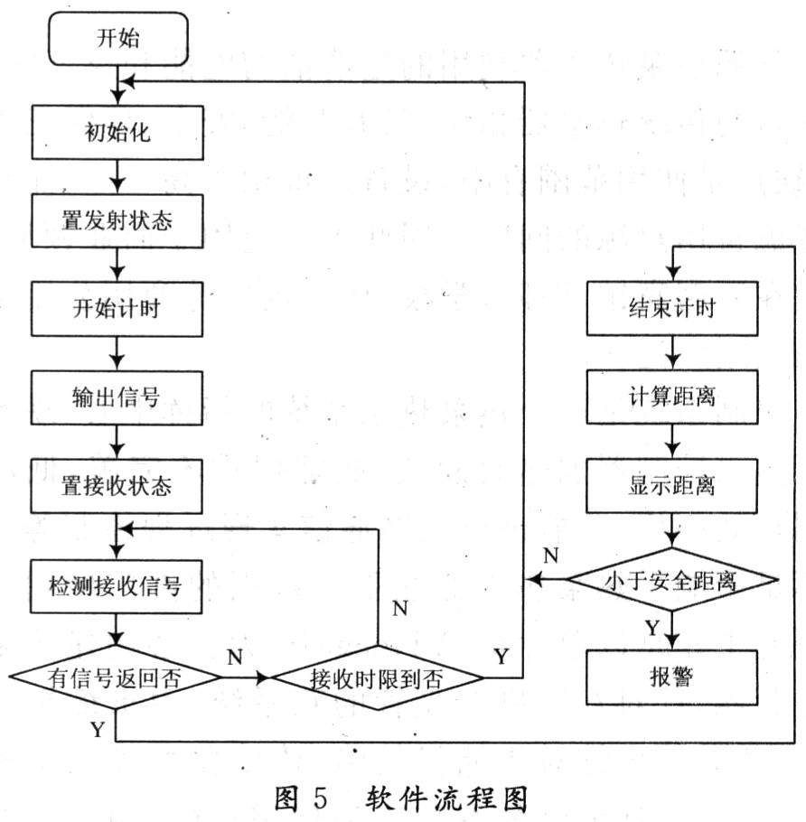
Plate non-damaged desulfator with Smart pulse, Simple and Safe, Restore your battery when charging.
Most of Electric vehicle use lead-acid battery bank(12V /6V /8V cells packed in Series)as the power source, The design lifespan of battery is 2~3 years, but actually the battery is usually failure after 6~12 months used which State-of-capacity gradually decline and even some scraped. Through analysis by cutting a large number of failure batteries, the battery water loss and sulfation is quite prominent. Such as the phenomenon of battery sulfation and water dehydration can be effectively inhibited to prolong the service life greatly up to 2 times.
EV Battery Charging Restorer is a new generation of high-tech products developed specifically for restoring Electric vehicle battery when it is charging every time, it utilizes the energy from the charger when charging, generating electronic smart pulse with special frequency to be resonance with the thick lead sulfate crystals in battery charging process. Under the disturbance by the specific frequency pulse, the recrystallization of lead sulfate can be prevented effectively
Product features:
1. The use of advanced electronic pulse repair technology, no-damaged eliminate battery plate sulfation crystal. Recovery of battery capacity, ensure the EV driving mileage is longer.2. The connection with charger is simple, safe and convenient, and Smart Pulse Charging Restorer can be used in conjunction with the charger for each charging process. The problem of sulfation of the plate can be eliminated during every charging process.
3.It smartly identify 72V/60V/48V/36V battery bank Spec, automatically adapt to precise voltage, automatically adjust the restore electric pulse.This Battery pulse maintainer is suitable for the popular 72V~36V batteries of electric vehicles, buy a set, multi vehicles benefit in family.
4. A strict circuit filtering technique, does not repair your charger as a pulse, without changing the structure of the charger, does not affect the charging parameters of the charger, safe and carefree.
EV Battery Charging Restorer
EV Battery Charging Restorer,Electric Motorcycle Battery Restorer,EBike Power Battery Repair,Electric Cycle Battery Repair
Shenzhen Daceen Technology Co., Ltd. , http://www.daceen-sz.com