introduction
This article refers to the address: http://
With the development of society, cars are becoming more and more popular, automotive applications have become increasingly complex, and electronic drives are increasingly used. Therefore, it is not surprising that more innovative technologies and specialized technologies are applied in this field. . With the increase in the number of cars, the probability of traffic accidents increases, especially during nighttime driving. The two cars meet, and the control of the car headlights is an important issue. Currently, cars often include dynamic position control. Headlights, especially for high-intensity discharge (HID) xenon lamps, are critical for dynamic position control. However, headlamp positioning systems place very harsh environmental requirements on electronic components. How to reduce the complexity of headlight motion control design, save time and reduce cost has become an important topic in automotive electronics research. This paper introduces a low price, uniform function, based on LIN bus headlight movement for the requirements of automotive headlight control. The implementation of the control system, the combination of different stepper drives / controllers to achieve the optimal system design of the car headlight motion control system.
System hardware circuit design
The LIN standard defines a low-cost serial communication system for use in distributed electronic systems for vehicles. LIN complements existing multi-network combinations for vehicles, including the Controller Area Network (CAN) protocol. The LIN standard enables a cost-effective communication network for in-vehicle switches, smart sensors and brake applications. The communication protocol is based on the SCI (UART) data format, a single-master/multi-slave concept and a single-line (plus-ground) 12V bus.
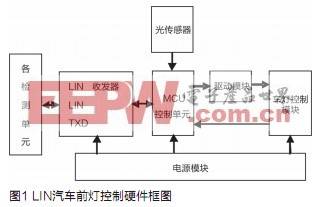
The LIN slave node processes the control signals sent by the node and measures the state of the lamp driver circuit. After receiving the message information from the node, the corresponding control signal is sent to the vehicle lamp, and the state of each lamp is analyzed. If a failure occurs, a data message is generated and sent to the total node. After detecting the signal sent by the total node, the LIN slave node first identifies through the message frame to see if it belongs to its own message information. If it belongs, it first determines whether the message is the query information, and if so, returns a response message. If it is the control information, it controls the corresponding lamp and measures the potential of the measurement point on the lamp driving circuit. Process it. See if it has failed. If a fault occurs, the information is sent to the total node via the LIN bus. And according to the sensor to detect the light signal of the car coming in front, make a judgment in real time, adjust the brightness and change of the light. Figure 1 shows the hardware block diagram of the LIN car headlight control.
MCU control unit
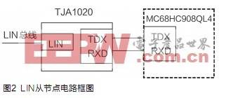
In the design, the MCU selects the MC68HC908QL4 of the Freescale M68HC08 series as the MCU of the LIN slave node, and its circuit block diagram is shown in Figure 2. The QL4 chip in the 16-pin TOP package, VDD is connected to +5V power supply, and the SLCTX and SLCRX pins are connected to the TXD and RXD pins of the LIN transceiver (TJA1020). The +12V LIN signal is input through the LIN pin of the transceiver, and is converted into a +5V receive and transmit signal through the transceiver, and transmitted to the QL4 accept and transmit pins respectively.
After the slave node is initialized, all other operations are completed in the interrupt. The SLIC Status Vector Register (SLCSV) provides an index offset that directly reflects the current working state of the LIN module. It can be used with the user-supplied jump table to quickly enter an interrupt service routine. All states of the LIN module have corresponding values ​​in the SLCSV, and their values ​​not only reflect the index offset of the LIN module state, but also reflect the priority of the interrupt.
LIN transceiver
This design uses TJAl020 as the LIN transceiver. TJAl020 is the interface between the LIN master/slave protocol controller and the LIN physical bus. It is mainly used as the vehicle sub-network. Its baud rate is 2.4~20kbit/s. The transmit data stream input by the controller at the TXD pin is converted to a LIN bus signal by the LIN transceiver, and the slew rate and waveform are controlled by the transceiver to reduce very low electromagnetic emissions (EME). The output pin of the LIN bus is pulled high by an internal termination resistor. The transceiver detects the data stream on the input pin of the LIN bus and sends it to the microcontroller via pin RXD.
Power module
In the design, the voltage regulator of the LIN module uses the micro power consumption, low dropout regulator LTll2l-5. By using LTl121-5 to input low level to SHDN, it can enter the stop mode. At this time, the quiescent current is only 16mA, so when there is no activity on the bus, the power consumption can be reduced. In addition, the device also has prevention. The reverse function of the input and output powers prevents reverse current flow even if the output does not add a diode.
Driver circuit module for headlights
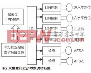
The designed lamp driving circuit module adopts distributed brake control, and its control frame is shown in FIG. This control is used for horizontal positioning, rotation and AFS of the dual headlights. The LIN Microstepping Motor Driver is a two-phase driver with a positioning controller integrated with LIN control/diagnostics that receives advanced positioning commands via the LIN interface and then drives the motor coil to the desired position. The on-chip position controller can be configured for different motor types, positioning distances, and parameters such as speed, acceleration, and deceleration. If the system detects a stall condition, sensorless stall detection prevents the positioner from stepping out and stopping the motor.
The high level of abstraction of the controller command set reduces the load on the microprocessor within the MCU. Adjusting the application is a straightforward method depending on the number of headlight motion control axes. Extending hardware and software design in a modular fashion does not seriously affect the requirements of the main microcontroller. This system uses only one MCU, and it is convenient and inexpensive to add or remove the optional motor when changing the system control function. Current vehicles often include headlights with dynamic position control. For high intensity discharge (HID) xenon lamps, this function is critical. European safety regulations require dynamic control of the vertical position of the main headlight beam to avoid glare. If a stepper motor driver chip is used, an integrated electronic motor driver circuit can be designed for similar applications where only a few passive components are required for these applications.
The driver chip obtains high-level positioning control and diagnostic command commands via a LIN, I2C or SPI bus and converts them into PWM signals that drive the stepper motor coils. Advantages of integrated motor driver circuits include increased system integration, reduced wire harness complexity, and reduced EMI emissions, which reduces system cost, speeds time-to-market and improves performance. Traditionally, automotive halogen headlamp systems are equipped with a manual adjuster to align the headlights in the vertical direction. The device includes an analog servo system that includes a drive, brushed DC motor brake that is driven to a position corresponding to a manually adjusted position. The feedback from the servo system uses a potentiometer connected to the end gear of the brake, which is an amplifier. The system is relatively inexpensive.
This design uses a vertical positioning method for linear stepper motor headlights. This type of motor is very robust and does not require potentiometer feedback when operating in open loop mode. Linear motion is achieved by a bolt/nut combination. The stepper motor that rotates around the bolt has a magnetic rotor that is driven by a control current in the stator coil. For halogen headlight horizontal positioning system, vertical positioning, fully adaptive front lighting system (AFS).
Car headlights are critical to the safety of the car at night. The motor that controls its position must also operate in an automatic mode. If the communication bus fails, turn the lamp to a safe position. This requirement means that the driver circuit must detect the stall position without the aid of an external sensor, and the microstepping mode ensures smooth and smooth motion. Therefore, for any headlight position control architecture, whether centralized or distributed, these functions are very basic features.
software design
The headlight control system mainly performs two functions: one is to realize the control of the LIN sub-node to the lamp; the other is to realize the diagnosis of the lamp failure. In the control, the system determines whether the system has failed by analyzing the potential of the bus potential and the input, output, and fault diagnosis pins in the drive circuit.
Software design is key to enabling LIN bus nodes to perform communication tasks efficiently and in real time. This design adopts a structured programming scheme with good modularity, portability and modifiability.
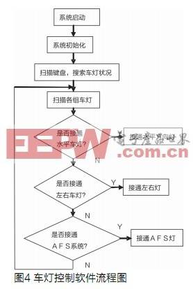
The LIN information is received by the interrupt mode. When the MC68HC908QL4 controller detects the information frame that meets the requirements of the node, it first determines what information is received by the local node, and if it is control information, it receives 2 bytes of data information; To query the information, the state of the local node headlights is sent back to the master node in the form of an information frame to reflect the node condition. It is then determined that if the data frame is received, the corresponding information is read on the data register (SLCDx) in the SLIC module. Finally, according to the relevant bits in the data information, the vehicle lamp control is performed. After the control signal is sent, the potentials of the input, output and fault diagnosis pins of the lamp driving chip are correspondingly collected, the movement state of the lamp is driven, and the horizontal direction lamp is turned on. Turn on the left and right direction lights and the AFS lighting system, and send a control signal to the drive circuit by analyzing and judging the potential. If it is not necessary to start the lights, send a return message and return to the position where the lights are scanned. The process of programming the lamp control is shown in Figure 4.
After the system is started and initialized, the meter module starts a timer to periodically scan the status of the dashboard light button, and then transmits the information to the vehicle light control module via the LIN bus. This information includes the driver. Requirements for the status of the lights (on or off). The lamp control module simultaneously detects the lamp information of the digital diagnostic output and the lamp of the analog current sensor diagnosis output, and transmits the faulty lamp information to the instrument module through the LIN bus. The transmission information includes the name of the lamp, the location of the lamp, and the state of the lamp. The lamp control module combines the judgment result of the instrument module and the scan result of the instrument panel to determine whether to turn on the lamp or turn off the lamp. The meter module receives/transmits information of the vehicle light control module via the LIN bus.
Conclusion
Based on the LIN bus headlight motion control system, the line can be diagnosed by the LIN bus. The system has the characteristics of simple structure, reliable performance, uniform functions and low price. For different stepper drive/controller combinations, A system design solution that optimizes the vehicle headlight motion control system. The hardware structure of the LIN node of the MCU+LIN interface chip is designed to realize the LIN network communication of the master/slave task. At present, how to adopt bus technology in China to improve vehicle performance and reduce manufacturing and maintenance costs has become a hot spot for auto manufacturers.
Nichrome Wire,Nicr 90/10 Wire,Nicr Wire
NiCr alloy Super alloy Co., Ltd. , http://www.chromiumaluminium.com