Central issue:
This article refers to the address: http://
Design an inertial vibration sensor
Establish a mathematical model of differential capacitive accelerometer and analyze its characteristics
solution:
The inertial mass is used to measure the acceleration by changing the gap between the detected electrodes under the action of external acceleration.
FET requires operation in the linear resistance region
Shift amplifier with high common mode rejection
introduction
Measuring the motion of the vibrating body relative to the earth or inertial space, an inertial vibration sensor is usually used. Inertial vibration sensors are available in a wide variety of applications. Accelerometers are available in piezoresistive, piezoelectric, and capacitive types. Among them, capacitive accelerometers have the advantages of high measurement accuracy, stable output, and small temperature drift. The capacitive accelerometer is actually a variable pole differential differential displacement sensor coupled with a "mkc" system. The measurement principle is to measure the acceleration by using the inertial mass to change the gap between the detected electrodes under the action of the external acceleration to cause a change in the equivalent capacitance.
Mathematical model of capacitive accelerometer
The principle structure of the capacitive accelerometer is shown in Figure 1. As can be seen from the figure, it is actually a variable pole differential capacitive displacement sensor, which is matched with a "mkc" system. The mass 4 is supported by the two spring pieces 3 in the casing 2, the capacitance C1 composed of the A surface of the mass 4 and the upper fixed plate 5, and the capacitance C2 composed of the B surface of the mass 4 and the lower fixed plate 1. .
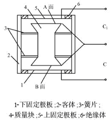
Figure 1 Schematic diagram of capacitive acceleration sensor
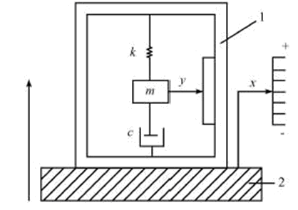
Figure 2 Schematic diagram of the “mkc†system
The equivalent schematic diagram of the capacitive accelerometer is shown in Figure 2. In Fig. 2, the right scale indicates a motion reference point that is relatively stationary with respect to the earth, called a static reference, and x indicates the displacement of the vibration body 2 and the sensor base 1 relative to the reference point, which is called absolute displacement, and y represents mass. The displacement of block m relative to sensor base 1 is referred to as relative displacement. The relationship between x and y can be described by a typical second-order differential coefficient equation:
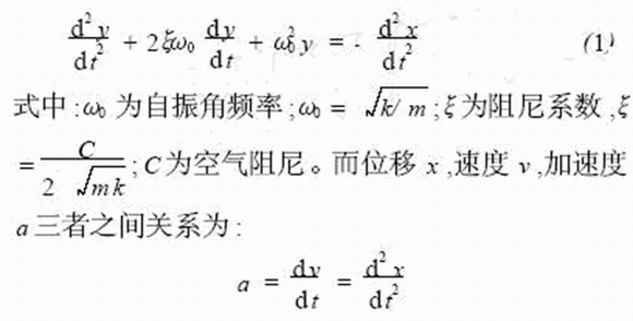
Substitute (1) is obtained:

The transfer function of the "mkc" system obtained by Laplace transform:

Let S=jω, the relationship between the displacement amplitude ym of the relative motion of the mass and the acceleration amplitude am of the absolute motion of the measured vibration body is obtained as follows:

Equation (4) has low-pass filtering characteristics. It can be seen that when ωn "ω0, then:
The displacement y of the sensor housing 2 is related to C1, C2 as follows:

Where d0 is the initial pole pitch of capacitors C1 and C2 when not vibrating. If the differential capacitor is connected to the transformer bridge shown in Figure 3, the open bridge output voltage amplitude U0 is:

Substituting equation (5) into equation (7)

It can be seen that when ω< <ω0, the output voltage amplitude U0 is proportional to the acceleration amplitude am, and the voltage amplitude U0 is measured to determine the acceleration amplitude am.
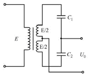
Figure 3 Transformer bridge
Differential capacitance calculation and characteristic analysis
For an air gap type capacitive sensor, the capacitance value is C=εS/d, and the two capacitances of the capacitive acceleration sensor are increased by one and decreased by one. Therefore, the total amount of capacitance change is:
g(9)
This is the equation for the relationship between the relative increment of capacitance and the relative increment of pole pitch. If the linear characteristic equation y = x is used, as shown in Fig. 4, it is obvious that the linearity error is large. For this purpose, the linear characteristic equation y = (1 + ε) x can be used, and the positive error ΔyM produced at the maximum range xM and the negative error Δy1 produced by x1 at it are numerically equal, ie:
Where ε is a certain positive fraction. Because the difference between the original equation and the linear equation is:

The position of the x1 point can be as follows:
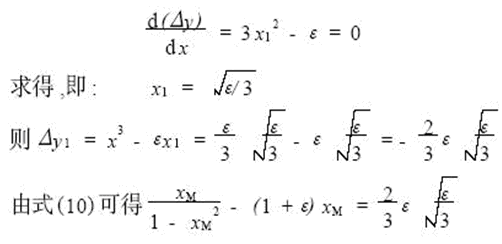
Assume
This can be calculated as:

Equation (12) shows the relationship between ε and xM under the condition that Δy1 = -ΔyM is satisfied.
Let the nonlinear relative error be γ, then

Substituting the formula (12) into the above formula, after finishing:
According to formula (13), the maximum range can be obtained according to a given nonlinear error, or the maximum nonlinear error can be obtained according to a given range. For example, if γ=0.01 is selected, then xM =1/5, that is, Δdmax=0.2d. Its characteristic analysis curve is shown in Figure 4.
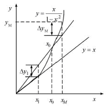
Figure 4 ΔC / C0 ~ Δd / d0 characteristic analysis curve
Circuit design
The circuit block diagram of this system is shown in Figure 5.
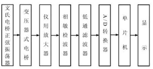
Figure 5 system circuit block diagram
Stable venturi oscillator
The stable venturi oscillator is an RC series-parallel frequency selective network sine wave oscillator with an operational amplifier as an amplifying component. The circuit is shown in Fig. 6.
Since the output resistance of the amplifier is very low, the feedback signal is added to the non-inverting input of the operational amplifier, so the input resistance is very high, so the gain of the non-inverting amplifier KF=1+ R8/Rf is only related to the external resistors R8 and Rf, but to the amplifier itself. The parameters are independent, so the accuracy and stability of the gain are high. In practical applications, R1=R2=R and C1=C2=C of the RC series-parallel circuit are often selected, so at the frequency of f=1/2πRC, the phase shift of the RC phase shifting network is zero, and R8≈2Rf, Meet the oscillation condition. Select R=240kΩ, C=330pF, then get the oscillation frequency as:
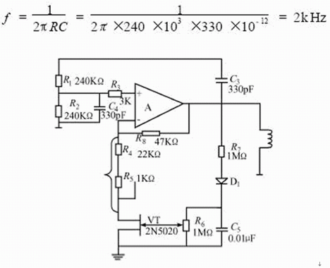
Figure 6 Steady venturi oscillator
For the purpose of automatic amplitude stabilization, a controllable negative feedback circuit consisting of R8, R4 and FET VT is added to the input of the operational amplifier. The FET is required to work in the linear resistance region. When the UDS is small, its RDS changes almost linearly with the gate-source voltage VGS, just like a good voltage-controlled linear resistor. The resistance can be adjusted from about 400Ω to 100MΩ. When the amplitude is large, the RDS should be automatically increased to enhance the negative feedback. This effect consists of the rectifying diode D1, the filter circuits R7, R6, C5 and the FET VT. When the amplitude is small, the voltage VC5 on C5 gradually decreases, causing the RDS to drop, so the circuit will automatically stabilize at one of the gate-source voltages of the VT, and output a sinusoidal voltage with a stable amplitude. Adjusting R6 can change the output voltage. Generally, the output voltage is adjusted between 3 and 5V.
b. Instrument amplifier
In many detection technology applications, the sensor output signal is often weak, and it also includes common mode interference such as power frequency, static electricity and electromagnetic coupling. The amplification of this signal requires the amplifier circuit to have high common mode rejection and high Gain, low noise, and high input impedance are customarily referred to as shift amplifiers, as shown in Figure 7.
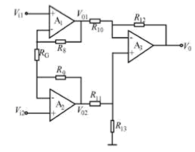
Figure 7 Instrument amplifier circuit diagram
The shift amplifier is known from the circuit structure. This is a non-inverting parallel differential amplifier. Its symmetrical structure makes the whole amplifier have high common mode rejection, especially for long distance measurement. Its mathematical model is:
Let the circuit parameters be symmetric R = R10 = R11 = R12 = R13 = 16kΩ, that is, R8 = R9 = 40kΩ.
Bringing equations (14) and (15) into (16) to get:
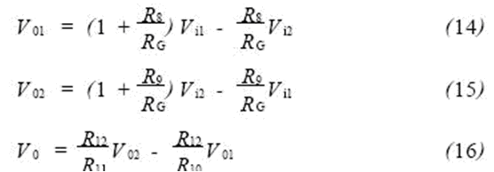

So the gain is:

This circuit features stable performance, greatly reduced drift, high input impedance and high common-mode rejection ratio, sensitivity to small differential mode voltages, and is suitable for long-distance transmission of signals, making it ideal for use with sensors. use. Obviously, to ensure the symmetry of the circuit, the most reasonable and simple way to change the gain is to change the resistance of RG.
c. Phase sensitive detector
After being measured by the transformer bridge, the weak AC signal is sent to the instrumentation amplifier for amplification. In order to restore the originally measured slow signal, the phase sensitive detector is used to convert the amplitude change of the AC into a proportional proportional to the sensor capacitance ΔC. DC level. Its phase sensitive detection circuit is shown in Figure 8. The working process is as follows:

Figure 8 phase sensitive detection circuit
When the input voltage Vi is a positive half cycle, the voltage V1 of the coupling capacitor C6 (ie, Vi = V1) is input to A4 inversion, D2 is turned off, D3 is turned on, and the voltage amplification factor of A4 is R16/R14=-1, that is, V1=-V2; adjust W2, R17=R19=20kΩ, the input signal of A5 sent by R17 and W2 is V1, and the input signal of A5 via A5 is V2, then the output signal is:

When the input voltage Vi is negative half cycle, it is inverted by A4, D2 is turned on, D3 is turned off, A4 output is zero, the input signal of A5 sent by R17, W2 is V1, and the other input signal of A5 is V1. Then the output signal V0 is:

It can be seen that the AC amplified signal Vi can reflect the amplitude of the signal voltage and reflect the polarity of the signal voltage after phase sensitive detection.
d. low-pass active filter
The low-pass active filter is shown in Figure 9. It consists of a passive RC filter and an active RC filter. The frequency characteristics of the passive RC filter are:

Where: ω1=1/R21C7 or f1=1/2πR21C7
The frequency characteristics of the active RC filter are:

Where: ω2=1/R24C8 or f2=1/2πR24C8
Then the frequency characteristics of the low-pass active filter are:

Therefore, its amplitude-frequency characteristics are:

Generally, the frequency at which the gain is reduced to KF/2 is the cutoff frequency. When f ≤ 11.5 Hz is obtained by the above equation, the bandwidth is 0 to 11.5 Hz. In this way, the higher harmonics in the pulsating DC signal after detection are filtered out. The advantage of using an active low-pass filter is that a smaller capacitor obtains a good filtering effect. The voltage signal after the filter output is connected to the single chip microcomputer 8031 ​​through the AD574 analog-to-digital converter, so that the detection and control of the measured object can be completed.
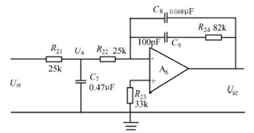
Figure 9 low-pass active filter circuit
Experiment and data analysis
Experimental equipment: One ZD-1 vibration table with a frequency response of 10 to 20 kHz. One type of 9102 vibration sensor, its performance index: sensitivity is 10pC/ms2, frequency response is 0.2-6000Hz, linearity is ±1%. BZ2112 vibration measuring instrument, its performance index: frequency response is 0.5Hz ~ 100kHz, the range is 0.1 ~ 1000ms -2 (0.01 ~ 100g). One device to be tested. During the experiment, the vibrating table works at 300 Hz. By adjusting the vibration amplitude of the vibrating table, the vibration measuring instrument's working range is from 0 to 100 ms -2, and the output voltage value of the device under test is read separately, and the characteristic analysis is performed. The test data is shown in Table 1:
Table 1 Filter output voltage values ​​of test equipment
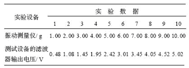
From the test data, the maximum error is 0.08, and the measurement range is 0-10g, so the linearity R=0.08/10=0.8%, which meets the design requirements.
in conclusion
The capacitive accelerometer designed in this paper has a simple circuit structure, a wide frequency range of about 0 to 450 Hz, a linearity of less than 1%, high sensitivity, stable output, small temperature drift, small measurement error, steady state response, and low output impedance. The relationship between the output power and the vibration acceleration is simple, convenient and easy to calculate, and has high practical application value.
Light reflectors in China with resonable price and good quality,We hope to establish cooperative relationship with you.
Light Reflector,Aluminum Light Reflector,Street Light Reflector,Energy Save Light Reflector
Yangzhou Huadong Can Illuminations Mould Manufactory Co., Ltd. , https://www.light-reflectors.com