The difference between power splitter and coupler

**First, the Power Divider Series** 1. Power dividers in the 400MHz-500MHz frequency range, available in two or three-way configurations, are commonly used in traditional radio communication systems, railway communications, and 450MHz wireless local loop applications. 
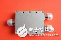
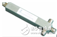
2. Two-, three-, and four-way microstrip power dividers operating between 800MHz and 2500MHz are ideal for indoor coverage solutions in GSM, CDMA, PHS, and WLAN networks. 3. Similarly, cavity-type power dividers in the same frequency range (800MHz–2500MHz) are also widely used in indoor coverage projects for the same communication standards. 4. For higher frequency applications, such as PHS and WLAN, cavity-type power dividers in the 1700MHz–2500MHz range provide reliable signal distribution. 5. Microstrip power splitters in the 800MHz–1200MHz and 1600MHz–2000MHz bands are designed for compact devices where space is limited.

The difference between power splitter and coupler

There are three main types of couplers, and their applications are similar to those of power dividers. Therefore, they won’t be repeated here. **Second, the Coupler Series** Couplers come with different coupling levels, including 5dB, 7dB, 10dB, 15dB, 20dB, and 25dB. 1. Microstrip couplers operating in the 800MHz–2500MHz frequency band. 2. Cavity couplers in the same frequency range (800MHz–2500MHz). 3. Cavity couplers specifically designed for the 1700MHz–2500MHz range.

The difference between power splitter and coupler

A combiner is a passive device that merges signals from different frequency bands into one output. The loss and performance characteristics vary depending on the design. Power splitters and couplers are both used for distributing RF signals, but they function differently. A power splitter evenly divides the input signal into multiple outputs, while a coupler provides unequal power distribution between the through and coupled ports. Both components introduce some level of insertion loss. Passive RF components can be either microstrip or cavity-based. Microstrip designs use a quarter-wavelength transmission line, while cavity-based units rely on resonant cavities. Microstrip devices are cost-effective but have higher insertion loss (around 0.5dB), whereas cavity types offer lower loss (about 0.1dB) but at a higher price. Power splitters are the most common passive devices for splitting a single signal into multiple equal parts. They are often used in two-way, three-way, or four-way configurations. When used in reverse, they act as combiners. Couplers, on the other hand, divide a signal into two unequal parts. They have three ports: input, through, and coupled. Based on the power difference between the through and coupled ports, they can be classified into various coupling levels like 5dB, 10dB, 15dB, etc. Some couplers also have specific ratios, such as 1:1, 2:1, or 4:1. The 3dB bridge is a special type of coupler with two inputs and two outputs, providing equal power distribution. It’s often used in base station applications, effectively acting like a two-way power divider. Combiners are used to merge signals from different systems, such as GSM, PHS, WLAN, and WCDMA. They require filters to prevent interference between frequency bands. While power splitters can sometimes be used as combiners, there are differences in performance, such as insertion loss, isolation, and power handling. For example: 1. **Two-way power splitter vs. 3dB bridge**: - A two-way power splitter typically has an insertion loss of around 3.8dB and 25dB of isolation. It has one input and two outputs, but it may have a high VSWR. - A 3dB bridge has lower insertion loss (around 3.2dB), similar isolation, and better flexibility in configuration. It allows for more flexible setups, such as two inputs and one output, or two inputs and two outputs. However, it is generally more expensive. 2. **Two-way power splitter, 3dB bridge, and combiner**: - Combiners are frequency-selective and can combine multiple signals with high isolation. They are best suited for merging different frequency bands. - The 3dB bridge is limited to combining two signals and has lower isolation. - Power splitters are simple and cost-effective but offer lower isolation and only one output. Each component has its own advantages and limitations, and the choice depends on the specific application requirements, such as frequency range, power levels, and system compatibility.

POE Adapter

POE Adapter, also known as a Midspan, Power Injector, or PoE Charger, is a device that leverages Power over Ethernet (PoE) technology to transmit both power and data simultaneously over an Ethernet cable. This technology enables the delivery of electrical power along with data signals to powered devices (PDs) such as IP cameras, wireless access points (WAPs), and more, over a single Ethernet cable.
Applications
POE Adapters are widely used in scenarios requiring remote power supply and data transmission, such as intelligent security systems (IP camera surveillance), wireless network coverage (WAP deployment), VoIP telephony systems, and more. These applications often demand devices to be installed remotely without local power sources, making POE Adapters an ideal solution.
Selection Criteria
Compatibility: Ensure the POE Adapter is compatible with your network equipment, particularly in terms of PoE standards and power requirements.
Brand and Quality: Opt for reputable brands and high-quality products to guarantee stable and safe power supply.
Power Rating and Port Count: Choose a POE Adapter with the appropriate power rating and number of ports based on your specific needs.
Saf

Poe Adapter,Ubiquiti Poe Adapter,Carrier Poe Adapter,Poe Power Adapter

Guang Er Zhong(Zhaoqing)Electronics Co., Ltd , https://www.geztransformer.com

This entry was posted in on