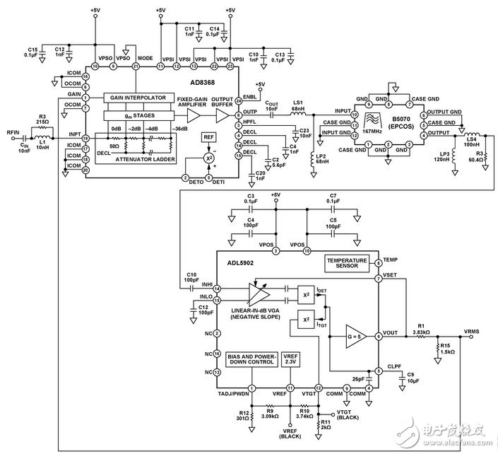
The 65 dB range of the ADL5902 linear dB true RMS response RF detector can be extended by a separate variable gain amplifier (VGA). The gain control input of the VGA is taken directly from the ADL5902VOUT pin. It extends the dynamic range according to the VGA gain control range (in practical applications, the range extension obtained is slightly smaller). If the VGA also provides linear dB (exponential) gain control, the total measurement range will remain linearly scaled in dB. The VGA gain must decrease as its gain offset increases, in the same way as the ADL5902. The AD8368 can meet all of these conditions. Figure 1 shows the circuit schematic.
The ADL5902RMS calculation circuit uses a VGA hierarchical architecture. The internal linear dB VGA has a negative gain control slope that drives the input of a narrow range RMS detector. The detector's output level is compared to the second setpoint detector output by a current balancing architecture; one detector provides current while the other detector draws current. If the output levels of the two detectors are not equal, the residual current will charge or discharge the capacitor; the capacitance is equal to the parallel combination of the internal 26 pF capacitor and the external capacitor on the ADL5902 pin 6 (CLPF). This configuration will cause the VOUT value to rise or fall. Since VOUT is directly connected to the gain control input of the ADL5902 VGA, this will cause the VGA gain to rise or fall until the output levels of the two detectors are equal. At this point, the VOUT and VGA gains are completed. Since the ADL5902VGA has a linear dB transfer function, the VOUT output voltage is proportional to the logarithm of the RMS value of the input signal.
The detection range of the ADL5902 is primarily determined by the gain control range of its internal VGA. Because the input signal drops as the range increases, the VGA control voltage also drops until the VGA reaches the maximum gain. For large input signals that are rising, the VGA gain control voltage also rises (and thus the VGA gain decreases) until the minimum gain is reached. Adding an additional variable gain to the signal path increases the detection range of the circuit. At this point, the VOUT feedback signal simultaneously drives the VGA gain control inputs of the ADL5902 and AD8368. The AD8368MODE pin must be tied low to make the gain control slope negative. Since the AD8368VGA provides gain and attenuation (GMAX = 22 dB, GMIN = −12 dB), the upper and lower limits of the ADL5902 nominal measurement range can be extended simultaneously. However, to achieve an optimized range expansion, the voltage driving the AD8368 gain control pin must be properly adjusted.
Although the ADL5902RMS detector has a nominal output voltage range of 0 V to 3.5 V, the AD8368VGA requires a 0 V to 1 V control voltage range to fully achieve its 34 dB gain control range. Therefore, the VOUT feedback voltage must be scaled down by a factor of 3.5. This is easily accomplished using a resistor divider (R1 and R15 in Figure 1).
Courtyard lights without solar power, just connect with the grid,suitable too for parks and landscape lighting. Their bright LED lights have a long, reliable life and can be easily installed in any location.They are inexpensive and available in a wide variety of colors and designs.can be customized by the height of the pole and the modeling.usually we made 3-3.5 meters high pole,with LED light lamps.we produce various kind of courtyard lights just as you customized.
Courtyard Light AC,Yard Lights AC,Garden Lights AC
Yangzhou Beyond Solar Energy Co.,Ltd. , https://www.ckbsolar.com