With the rapid development of the battery industry, major battery manufacturers at home and abroad have invested a large amount of money and R & D personnel to develop large-capacity high-energy-density power batteries based on small-capacity batteries. Lithium batteries are widely used in electric vehicle automotive energy systems, aerospace power systems, solar photovoltaic power systems, etc. due to their high operating voltage, small size, light weight, no memory effect, no pollution, low self-discharge, and long cycle life. in. The detection and formation of the battery is a key process in the production and use of the battery, which is related to the quality and quality of the battery, and directly affects the production cost and service life of the battery.
First, the system structure
The overall structure of the system is shown in Figure 1.
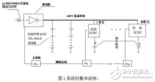
The whole system is mainly composed of four parts: rectifier cabinet, energy storage battery pack, chemical conversion module (bidirectional DC/DC), and centralized computer control system.
1 rectifier cabinet
It is mainly used for initial charging and daily supplementary charging of energy storage battery packs.
2 energy storage battery pack
It is used to balance the impact of the charging/discharging process between the various forming units on the 400V DC busbar (similar to the effect of the pool), which can be composed of lower cost or different types of batteries.
3 formation module (bidirectional DC / DC)
When the battery unit is charging, the DC bus power supply is taken in units for charging. During discharge, the DC/DC transducer converts the energy of the single cell into energy above 400V, charging the energy storage battery pack through the bus. The DC/DC unit is the latest high-frequency high-efficiency module with an efficiency of 94~96%, which can save energy loss caused by discharge process by about 90~93%.
4 centralized computer control system
PC1 to PCN are used for operational control and data acquisition of each formation/detection work. PC0 is the main control machine (may be several) used for the management of the entire production workshop, and the simulation control of the working conditions between the work is carried out to ensure the smooth flow of the entire production process, and the data processing is saved and filed.
Job Description:
When a single battery is charged, energy is supplied from the grid, and the battery is subjected to constant current charging through a rectifier cabinet and a chemical conversion module (bidirectional DC/DC); when discharging, the energy of the battery is converted into a module (two-way DC/DC) for the energy storage battery pack. Discharge
A more important advantage of the system is that multiple batteries are simultaneously formed, some of which are charged and some are discharged. A DC bus is designed for this purpose to connect the rectifier cabinet to several compound modules (bidirectional DC/DC). In this way, the energy can flow between different battery cells through the DC bus, avoiding the separate design of the circuit for returning energy for each discharge module, which can improve the efficiency of the entire device and reduce the equipment cost. In addition, under the control of the control system, the energy balance control strategy is adopted. By controlling the working time of different charging and discharging modules, the charging energy is equal to the discharging energy as much as possible, and most of the energy flows only between the DC bus and the single battery. Through the power grid, the energy converted from the grid and the energy stored in the energy storage battery pack balance the energy difference between the charging and discharging, which can further improve the efficiency.
The voltage of the DC bus is selected as 400V. The main purpose of the high-voltage DC bus design is important for the formation module (bidirectional DC/DC) and parallel connection on the DC bus. The higher the DC bus voltage, the smaller the line loss, but not too high. Failure to do so may result in difficulty in selecting power electronics and a problem in that the bidirectional DC/DC voltage ratio or step-down ratio is too large.
The centralized computer control system design is mainly for the battery formation process requirements. In the battery formation process, a small number of personnel are required to monitor a large number of chemical cells. In order to improve efficiency and reduce labor intensity, centralized management and monitoring must be adopted. It is very important to charge or discharge the battery data in the battery formation. It is the basis for identifying the battery quality and the battery group screening. The database must be built by the computer system to store the data.
A CAN communication network is used between the control system and the conversion module (bidirectional DC/DC) and the rectifier cabinet. Currently, CAN networks are widely used.
Second, the rectifier cabinet design
Adopting the mainstream LLC resonant soft-switching rectifier circuit, the charging efficiency is greater than 96%. The input total harmonic distortion is less than 5%. The function of the rectifier cabinet is to supplement the power loss during the battery formation process. When the discharge energy is greater than the charging energy, the bus voltage will rise and the bus will charge the energy storage battery pack. When the charging energy is greater than the discharging energy, the bus voltage will decrease, and the rectifier absorbs the grid energy to maintain the bus voltage stability. Its topology is shown in Figure 2.
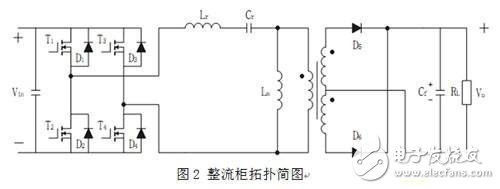
The topology is LLC resonant full bridge Vin for AC rectification (å phase passive PFC) or PFC (power factor correction) post voltage
T1, T2, T3, and T4 are MOSFETs Lr is a resonant inductor Cr is a resonant capacitor D5, and D6 is a high-frequency rectifying diode Cf as a filter capacitor.
The control switch is a special switch for process control of electrical control and thermal instrumentation. Specifically, there are positioning operation, self-resetting operation, positioning-self-resetting operation, blocking operation, positioning-blocking operation, self-resetting-positioning-locking operation and so on.
The types of Control Switches are:
ME Limit Switch
Micro Switch
QS5 Cam Switch
Universal Changeover Switch
Foot Switch
Proximity Switch (Sensors)
Switching Power Supply Unit
Float Switch
Weather Proof Isolating Switch
Isolating Switch and Changeover Switch
Control Switches
Control Switches,Float Switch,Proximity Switch,Cam Switch
Ningbo Bond Industrial Electric Co., Ltd. , https://www.bondelectro.com