As a combination of high-tech and technology, intelligent robots directly reflect the development level of a country's information technology and have received great attention from all walks of life. Intelligent robots involve almost all aspects of information technology, allowing students to access and see the panoramic view of information technology, and intelligent robots are an open platform for information technology, students can fully use their imagination to develop a variety of smart devices, thus cultivating students The ability to develop information technology, in the development process, to develop a variety of abilities to stimulate students' interest.
The TMS320LF2407A educational robot hardware platform based on smart car is designed in this paper, including the power module and motor drive module circuit design, and integrates infrared and photosensitive sensors and wireless data transmission module. Through software design, tracking and obstacle avoidance can be realized. The combination of tracing and obstacle avoidance achieves the combination of theoretical course learning and hands-on practice, which consolidates knowledge and further enhances learners' interest.
1 Design ideas and overall plan
1.1 The design idea of ​​educational robot
The educational robot is based on the TMS320LF2407A microcontroller. The external environment information collected by various sensors such as infrared sensors and photoelectric sensors is used as an input signal. The DSP performs arithmetic processing and uses PWM technology to output and adjust the speed and direction of the car in real time to realize the car. Automatic control functions such as tracing, obstacle avoidance, tracing and obstacle avoidance, and the car has been traced
When encountering obstacles in the process, when the tracking and obstacle avoidance algorithm can not complete the obstacle avoidance function while tracing, the wireless communication transceiver module connected to the PC and another wireless transceiver module connected to the DSP can realize wireless short-distance communication. , control the car out of the obstacle zone and carry out normal tracing.
1.2 Overall design and block diagram
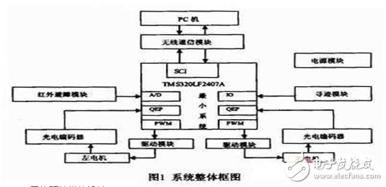
The overall block diagram of the robot car system is shown in Figure 1. It mainly consists of the TMS320LF2407A minimum system part, power supply module, motor drive module, sensor module and wireless communication module, which realizes the continuous transmission of information from various sensors on the vehicle to the on-board microcontroller. And download the programming design algorithm to the microcontroller to real-time adjust the motion state of the car to complete certain functional requirements.
2 system hardware module design
2.1 TMS320LF2407A minimum system design
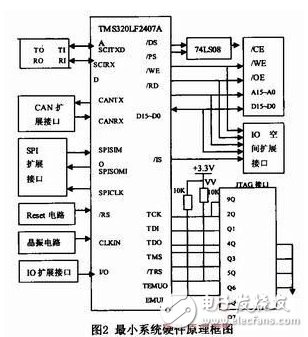
The TMS320LF2407A is the most widely used product in the 2000 series. It not only has an efficient processor for digital signal processing, but also integrates a large number of on-chip peripherals for memory and adaptive control applications, thus forming a basic On-chip computer system. In addition to the improved Harvard architecture, multi-bus structure and pipeline structure, it also uses high-performance static CMOS technology, the voltage drop is 3.3V, reducing power consumption, instruction execution speed is increased to 40MIPS, almost all instructions can be 2 5ns is completed in a single cycle. The basic structure of the TMS320LF2407A consists of three components: a central processing unit (CPU), memory, on-chip peripherals, and dedicated hardware circuitry. The hardware platform of the system makes full use of the characteristics of the TMS320LF2407A controller to adopt modular design, which is divided into basic circuit and extended control circuit. The basic circuit includes a power supply circuit, a reset circuit, a clock circuit, an A/D input channel, and a JTAG emulation circuit. The expansion circuit includes a memory and a decoding circuit, a serial communication SCI and RS-232 interface circuit, a CAN interface circuit, an SPI function module, and the like. The system hardware block diagram is shown in Figure 2.
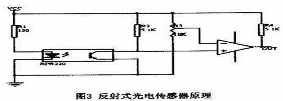
This part uses photoelectric sensors to identify road surface information. Using RPR220 photoelectric pair tube, RPR220 is an integrated reflection type photodetector whose emitter is a gallium arsenide infrared light emitting diode. The receiving tube is a high sensitivity silicon planar phototransistor, and three infrared pair tubes are used. The "one" shape is arranged at the bottom of the front of the trolley, and the path trajectory is indicated by the black line. The position of the detected black line photocell is determined according to the difference between the intensity of the reflected light received by the phototransistor falling in the black line region and the white area. To determine the direction of the car to see if it deviates from the black line. When the infrared diode of the tube emits infrared light and reflects it through the reflector (white line) to the receiving tube, the resistance between the collector and the emitter of the receiving tube becomes smaller. The potential at the input terminal becomes low, and the low level is output after comparison by the comparator. When the infrared ray is irradiated onto the black line, the light reflected to the receiving tube is reduced, and the resistance between the collector and the emitter of the receiving tube is increased to make the output high. Level, the output signal is sent to 2407A for analysis and processing. The principle of reflective photoelectric sensor is shown in Figure 3. If the middle sensor (middle sensor) detects a black line among the three sensors, the slave will send a "wired" signal, and the two motors of the rear wheel will continue to operate, and the vehicle body will be driven forward. If no black line is detected by any of the left and right sensors except the middle sensor, the sensor outputs a "wireless" signal, at which time the drive motor on the opposite side of the sensor that is off the guide line stops running, and the same side motor continues to run. In order to achieve the purpose of correcting the direction of travel.
Pcb Pluggable Terminal Block Connector ,Pluggable Terminal Block,Contact Pluggable Terminal Blocks ,Pluggable Screw Terminal
Cixi Xinke Electronic Technology Co., Ltd. , https://www.cxxinke.com