A pulse power supply is designed to provide intermittent power to a load, following a specific time-based pattern. This means the power is turned on for a certain duration, then turned off for another period, forming a repeating cycle. This on-and-off operation creates what is known as a pulsed power supply.
Understanding the key electrical parameters of a pulse power supply is essential for proper setup and operation:
1. **Output Voltage**: This refers to the peak voltage difference between the red and black terminals of the output. The value shown on the panel represents the absolute voltage difference when connected.
2. **Output Current**: The effective current in the output loop equals the product of the peak current and the duty cycle during the on-time.
3. **Duty Cycle**: This is the ratio of the high-level time (pulse width) to the total cycle time. Duty Cycle = Pulse Width / (Pulse Width + Interpulse).
4. **Output Frequency**: This is the inverse of the total cycle time, representing how often the on-off cycle repeats per second.
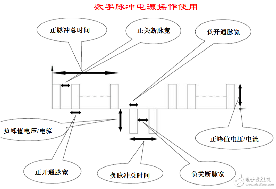
5. **Pulse Width (Pulse Duration)**: The time the power is applied within one cycle, denoted as 't'.
6. **Pulse Interval (Interpulse)**: The time between pulses when the power is off, denoted as 'Tt'.
7. **Commutation Time**:
- **Forward Commutation Time**: The total time during which the output has a positive voltage.
- **Reverse Commutation Time**: The total time during which the output has a negative voltage.
**How to Set the Parameters:**
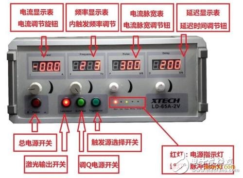
1. Connect the AC 220V 50Hz power supply as required, and turn on the power switch to check if the system operates normally.
2. Turn off the pulse start switch (press to start, release to stop). Then configure the positive and negative pulse settings: set the total positive time, the on-pulse width, and the off-pulse width. (Refer to the diagram above.)
Typically, the total positive time should be longer than the negative time. Otherwise, the metal may be stripped away during the negative pulse phase and not plated at all.
*Note: The total time must be greater than the sum of the on and off pulse widths; otherwise, there will be no output.*
*For example: If the total time is 2000 ms, the on-pulse width is 10 ms, and the off-pulse width is 2 ms, the pulse frequency would be 166 Hz.*
3. When using a single pulse, set the negative pulse parameters (total time and on-pulse width) to zero.
4. For DC operation, set the negative parameters to zero, maximize the total time, set the on-pulse width close to the total time, and minimize the off-pulse width.
5. Press the pulse start switch to begin the process.
6. Click on the display screen to enter the parameter settings. In most cases, especially during precious metal plating, you'll set the positive and negative voltage values and press the start button to initiate the process.
7. Once running, you can monitor the peak voltage and current of both the positive and negative pulses directly on the display. You can also adjust these values dynamically while the system is operating.
8. Any changes to the pulse parameters must be made when the pulse start switch is in the off position. The new settings will only take effect once the pulse is restarted.
Pet Circuit Layer Membrane Switch,Customzied Membrane Switch,Flexible Circuit Membrane Switch,Circuit Membrane Switch
CIXI MEMBRANE SWITCH FACTORY , https://www.cnjunma.com