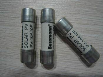
 I. Relevant national standards 1. In the low-voltage shunt capacitor standard GB/T12747.1-2004, the relevant requirements and instructions for the maximum current and protection of the relevant capacitors are as follows:
 The capacitor unit shall be suitable for continuous operation with a line current rms value of 1.3 times the unit's current at the rated sinusoidal voltage and rated frequency, except during the transition. Taking into account the capacitance deviation, the maximum capacitance up to 1.10CN, so the maximum current up to 1.43IN.
These overcurrent factors are the result of a combination of harmonics, overcurrents, and voltage deviations.
33 Overcurrent The capacitor must not operate at currents exceeding the maximum values ​​specified in Chapter 21.
34 Switches, Protection Devices and Connections Switches, protection devices and connections shall be designed to withstand continuously 1.3 times the current drawn at nominal frequency and sinusoidal voltage equal to the rated voltage. Because the capacitor's capacitance may be 1.10 times the rated value, this current is a maximum of 1.3×1.10 times the rated current, which is 1.43IN.
2, in the low-voltage capacitors and complete sets of standard GB7251, the choice of capacitor protection fuses requirements are as follows:
5.3.5b)
The rated working current of the fuse (square root value) shall be selected from 2 to 3 times the rated current of the single capacitor.
3. In the design specification for parallel capacitor devices GB50227-2008, the requirements for capacitor protection fuses are as follows:
5.4 Fuse 5.4.2 The fuse rated current of the external fuse for single capacitor protection shall be selected according to the capacitor rated current of 1.37~1.50.
Second, the standard analysis Through the analysis of the above criteria, we can draw the following conclusions:
1. In the above standards concerning low-voltage capacitors or capacitance compensation devices, the selection requirements for protection fuses are based on the application of simple capacitor compensation, that is, we often say pure capacitance compensation. However, for the application of more and more widely used non-tuned compensation (capacitor series reactor), there is no explanation on how to select a protection fuse.
2. Even for pure capacitance compensation applications, the selection requirements for protection fuses vary from standard to standard. However, from the technical basis and the degree of detail of the standard requirements, GB/T12747.1-2004 has a more reasonable selection of protection fuses (1.10×1.3=1.43IN), but it is not perfect because of the overcurrent of some capacitor products. The capacity has reached 1.5 times, not 1.3 times that required in the standard.
3. For non-tunable compensation (capacitor series reactor) application of the fuse selection, there is no standard for reference.
Third, how to correctly choose low-voltage reactive power compensation protection fuse According to the analysis of the relevant national standards, and the two main types of low-voltage reactive power compensation mentioned above, the correct choice of low-voltage reactive power compensation fuses should be from the following two Aspects are considered and selected separately:
1. Pure capacitance compensation application, only low voltage capacitors for compensation components:
Due to the rationality of the national standard GB/T12747.1-2004, the requirements for the maximum allowable current in this standard can be used to refer to 1.10×overcurrent capability×capacitor rated current to select the protection fuse.
An example of a capacitance compensation loop with 25KVAR/400V:
1) The rated current of the capacitor in the circuit is 36A. If the capacitor only meets the 1.3 times overcurrent capability in the standard, the maximum allowable current of the circuit is 1.10 x 1.3 x 36 = 51.5A. The fuse's standard current range includes 50A, 63A, so the correct fuse rating should be 50A.
2) If the capacitor is larger than the overcurrent capacity in the standard, such as 1.5 times, the maximum allowable current of the circuit is 1.10 x 1.5 x 36 = 59.4A. The standard current range of the fuse> includes 50A, 63A, so the rated fuse of the correct fuse should be 63A. .
2. Non-tuning compensation applications. Compensation components include low-voltage capacitors and series reactors:
This kind of application is a reactor with a certain reactance rate connected in series in the traditional capacitor compensation loop. Its advantage is that it can prevent the harmonic amplification of the system and avoid resonance, and at the same time it can absorb some harmonics in the system, thus providing reliable reactive power. At the same time, the compensation has the purpose of improving the power quality, and it has been increasingly applied in industrial and building distribution systems.
When considering fuse protection in this application, the capacitor and the series reactor should be analyzed as a whole, because in addition to the normal fundamental reactive current, the compensation loop should allow it to carry a certain amount of harmonics. Wave current.
More importantly, since the capacitor rated voltage of this application is much larger than the voltage of the distribution system (eg, the rated voltage of the capacitor is 525V, much larger than the 400V system voltage when the 14% reactance rate is applied), the capacitor can actually carry the load in a 400V system. The current (including fundamental and harmonic currents) is greater than its rated current at rated voltage (eg, 525V). Therefore, in this type of reactive power compensation application, the parameters of the series reactor, that is, the maximum overcurrent capability of the reactor, determine the loop overload capability.
Therefore, the choice of fuse should be based on the rated current of the circuit and the maximum over-current capability of the reactor. Take a 25KVAR/400V compensation circuit with a reactance rate of 14% as an example:
The rated current of the capacitor in the circuit is 36A. If the maximum overcurrent capacity of the reactor is 1.8 times the rated current, the maximum allowable current of the circuit is 1.8×36=64.8A, so the rated rated current of the correct fuse should be 63A.
Mass PCB Assembly = Mass Rigid Printed Circuit Board Assembly, which means quantity is big and need do big production assembly. For production PCB assembly job, the SMT assembly would all by machine and would do IPQC for checking the first sample quality to ensure the SMT line is reliable. Zhongfeng would manufacture the rigid PCB boards follow the design file, source the components follow the BOM file and do the PCB assembly job follow the assembly drawing and the pick&place file. After PCB assembly done, the components would be mounted on the PCB boards tightly and connected each other through the copper circuits. We call such board as PCBA board or mass PCBA board.
Depends on the components assembly types, it have THT PCB assembly, SMT PCB Assembly , one sided SMT and THT PCB assembly, two sided SMT and THT PCB assembly.
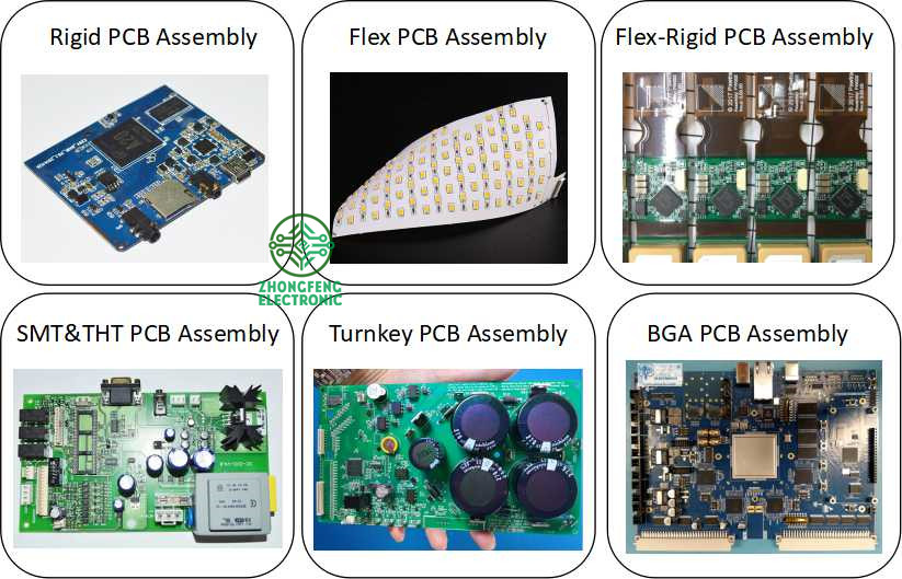
Depends on the PCB type, it have Rigid PCB Assembly, Flex PCB Assembly and Flex-Rigid PCB Assembly.
Also we would call some PCB assembly types as Prototype PCB Assembly, Mass PCB Assembly , Turnkey PCB Assembly, LED PCB Assembly and BGA PCB Assembly , etc.
With our 15years professional experience, we are available for all types of PCB assembly service from prototype to mass production, available for 01005, 0201, 0.3mm BGA, 0.3mm QFP.
PCB Assembly Capabilities
|
Quantity |
1 pcs - 1,000,000 pcs |
|
Assembly type |
SMT, THT or Hybrid |
|
Parts procurement |
Full turnkey (ZhongFeng provide all components) |
|
Partial turnkey ( Customer provide the main components and ZhongFeng provide the rest) |
|
|
Kitted (Customer provide all components) |
|
|
Component types |
SMT 01005, 0201, BGA 0.3mm pitch, QFP 0.3mm pitch, etc. |
|
Test |
Visual Inspection, AOI, Custom testing, ICT, FCT, Test jig |
PCB Assembly Products Show

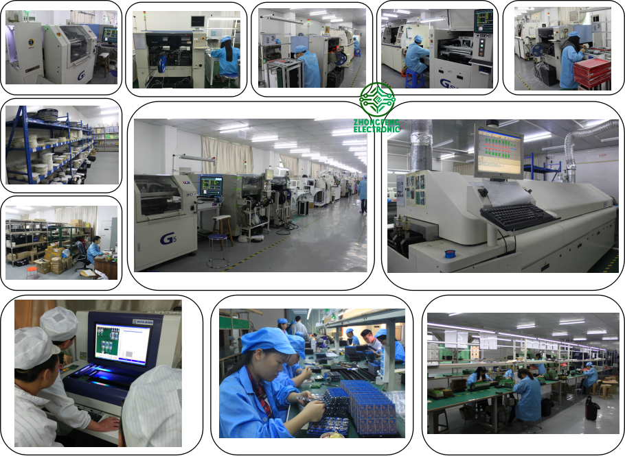
PCB SMT Assembly Factory Show


Mass PCB Assembly
Mass PCB Assembly,PCB Mass Production,Mass Quantity PCB Assembly,Mass PCB Board Assembly
ZhongFeng Electronic Technology Co., Limited , https://www.dopcba.com