Overview
Semiconductor junctions (from millions of transistors in an IC to large-area composite junctions that implement high-brightness LEDs) can fail early due to the heat that is constantly being generated. This becomes a very serious problem when the feature size is reduced and the current demand is increased, and even normal operation may accumulate heat and increase the junction temperature. An increase in temperature may increase the number of defects in the junction, resulting in reduced performance and reduced life cycle of the device.
The SMU is connected to the device using a four-wire measurement method or a Kelvin measurement method. By sensing the voltage at the input of the DUT[device under test] instead of the SMU [source measurement unit] source measure unit., the four-wire voltage measurement can reduce the error caused by the lead resistance in the voltage measurement.
This paper mainly discusses the measurement of junction temperature from the following four aspects (temperature measurement method, junction temperature test method, application example, error source).
Temperature measurement method
An accurate temperature measurement method is needed to measure the temperature of a semiconductor device to avoid high temperatures that may cause failure. One method is simple: measure the junction temperature. It can use common test and measurement instruments, and measurement results can be used to monitor the operation of a particular device. The ideal way to measure junction temperature is to monitor the component temperature as close as possible to the heat source. The current flowing through the semiconductor junction generates heat that flows through the junction material to the outside world.
Another method is to place the temperature sensor very close to the semiconductor junction and measure the output signal of the sensor. As the heat flows to the outer area, the temperature of the outer area and the sensor rises. Although this is a very straightforward process, this method has many physical limitations due to the limited size of the sensor. In many cases, the sensor itself is larger than the size of the node to be measured, which adds a lot of heat to the system and introduces additional measurement errors, which reduces measurement accuracy. Therefore, this method is useless for most applications.
Test Equipment
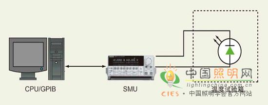
Figure 1: In the test setup, the SMU is used to describe the relationship between the forward voltage drop of the semiconductor and the junction temperature.
SMU [source measurement unit] source measure unit
A better solution is to use the node itself as a temperature sensor. For most materials, there is a close correlation between the junction forward voltage drop and the junction temperature. When the junction forward voltage drop is nonlinear with the junction temperature depends on the material and design of the junction. In normal operating environments with temperatures up to 80 ° C to 100 ° C, it is safe to assume that the junction forward voltage drop and junction temperature of most materials are linear. The nonlinear characteristics can be determined experimentally by measuring the voltage at higher ambient temperatures until the junction forward voltage drop and the junction temperature are non-linear. For most devices, this relationship is close to a linear relationship and can be expressed in mathematical formulas as follows:
TJ=(m×VF)+T0 (1)
Where TJ = junction temperature (unit: °C); m = slope {device-related parameters (related to chip substrate material, chip structure, package structure, emission wavelength, etc.), unit: °C / V }; VF = forward voltage drop; T0 = intercept (parameters related to the device, unit: °C).
At a given temperature (TJ), the forward voltage drop (VF) of the semiconductor junction is constant. If we measure VF at two different temperatures, we can calculate the slope (m) and intercept (T0) of a node. Since this is a linear relationship, we only need to measure VF to calculate the junction temperature in different states using equation (1).
TJ=(m×VF)+T0 (1)
If we know the TJ of different operating states and packaged devices, we can calculate the thermal parameters of different package types and designs, such as thermal resistance. This is especially important when designing specific operating conditions to ensure the longest device life, as thermal effects are the primary cause of early device failure.
Â