In recent years, with the continuous advancement of technology, the two-wheeled self-balancing trolley has achieved great development in many fields due to its simple structure, light weight, compactness, flexibility, and energy saving. In this paper, a two-wheeled car was designed and manufactured. The MK60DN512ZVLQ10 MCU produced by Freescale was used as the core controller. The accelerometer MMA7260 and the gyroscope ENC03 were used as the vehicle body attitude control measurement components to realize the self-balancing of the two-wheeled car. According to the deviation between the set speed and the speed of the trolley, the voltage of the motor is controlled to realize the speed control, and the linear CCD is used to collect the track information, and the steering speed of the two wheels of the trolley is controlled according to the curvature of the path, thereby realizing the steering of the two-wheeled vertical vehicle. Tracking scheme.
This article refers to the address: http://
1 system composition
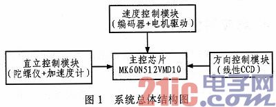
The system is mainly composed of functional modules such as single chip core controller, upright control module, speed control module and direction control module. The upright control module contains gyroscopes and accelerometers that are mounted at the center of gravity of the cart to ensure that the sensor is not too sensitive or too slow, and the data fusion between the two allows the cart to maintain a certain tilt angle. Speed ​​control module: The motor drive module drives the DC motor to run. The speed is measured by the encoder mounted on the left and right wheels, and compared with the set speed, the control car is driven at the set speed. Directional control module: The linear CCD installed on the bracket above the movement of the trolley controls the two wheels to realize differential turning to control the direction of motion. The system block diagram is shown in Figure 1.
2 individual control modules
2.1 Upright Control Module
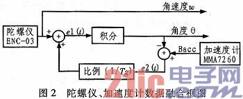
The first condition for the two-wheeled vehicle to walk is the upright balance of the car. The reference scheme we designed is shown in Figure 2. It collects the angular velocity w of the vehicle tilt by the gyroscope ENC03, collects the angle θacc of the vehicle tilt by the accelerometer, and compares it with the angle θ obtained by the gyroscope integration, and obtains the deviation amount e2(t) through the proportional 1/Tg conversion as the feedback amount. For the gyroscope, the deviation amount e1(t) is added to the angular velocity collected by the gyroscope and integrated as the angle θ of the vehicle tilt. Due to the gyro, there will be a point error.
Difference and temperature drift, the use of accelerometer can reduce the error of the gyroscope, the acceleration is relatively large due to external interference, the instantaneous value is not accurate enough, so with the use of the gyroscope, the two work together to capture the tilt angle of the car model.
2.2 Speed ​​Control Module
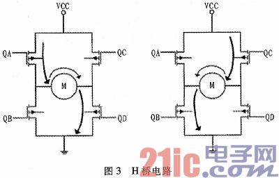
The motor drive uses four BTS7960 to form an H-bridge circuit to drive the rotation of the DC motor. In addition, the MK60N512VMD10 single-chip two-way pulse counter is used to measure the pulse amount of the left and right wheels of the car through the encoder. The four inverters are used to control the forward and reverse of the two motors. As shown in Figure 3, when the switches QA and QD are turned on, the motor rotates in the forward direction, and when the switches QB and QC are turned on, the motor rotates in the reverse direction, thereby realizing the forward and reverse rotation of the motor, and the magnitude of the current determines the rotational speed of the motor. The PWM duty cycle determines the magnitude of the current, which indirectly controls the speed of the motor.
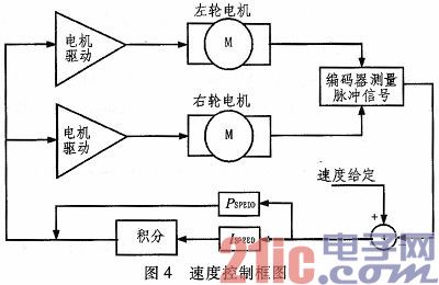
The speed control of the car is based on the upright of the car. By setting the speed of the car, then comparing the actual speed of the car measured by the encoder with the set speed, the deviation is used as the feedback amount, after the ratio PSPEED, integral The ISPEED sum as the output of the speed further controls the output of the PWM to cause the cart to travel at the set speed, as shown in Figure 4.
2.3 Direction Control Module
The running direction control of the trolley is realized by the differential speed of the two wheels, and the differential speed is determined by the linear CCD collecting the track information to calculate the deviation values ​​of the black lines on both sides of the curved line and the straight line on both sides of the straight road. The CCD model used in our competition is TSL1 401, which is a linear CCD. Compared with the area array CCD, the linear CCD only collects one line of data, and this line of data is the image gray collected by the linear CCD sensor 128 photodiodes through the integration circuit. Degree value.
For the 128 data collected, it is necessary to determine a threshold Th, which is generally about 200 (you can also select several different thresholds Th according to the brightness of the scene environment through the dial switch) to distinguish the white runway from other colors. Non-runway area. The value returned for the white runway must be greater than the value returned by other feedbacks. Take a median of these numbers as a threshold to distinguish the black and white points of the track (except for the white track, the rest are black dots). Discriminate
After the white runway, the deviation value from the normal runway can be calculated, and the deviation of the two sides can be subtracted and converted into a voltage value added to the direction output function to control the steering of the trolley. The block diagram is shown in Figure 5.
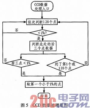
Since the track of the game has a dotted line, we will collect 128 points of data from the middle (the data of the 64th point) to the two sides (the left 64-0 is the same as the right 64-127), the purpose is Looking for the black points on both sides, if it is smaller than the threshold Th, it is judged whether the three points are smaller than the threshold Th, and if so, it is considered that the black line on the side of the track is detected.
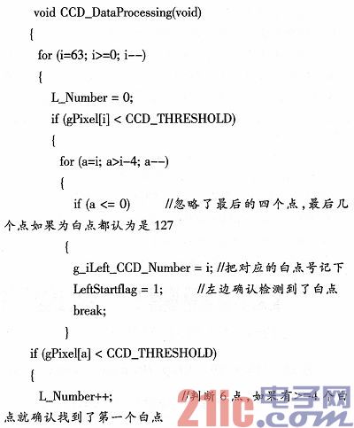
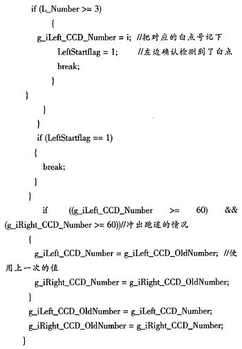
Program implementation part (64 point detection part of 64-0 on the left):
3 Conclusion
In this paper, the design idea and implementation method of two-wheel self-balancing trolley control system based on linear CCD are discussed. The direction control module for track recognition through linear CCD and the hardware and software of modules such as vertical control module and speed control module are completed. The analysis was carried out and the key blocks were given. By testing and participating in the Freescale smart car race, it proved that the system is reasonable and also improves the speed of the car running. Carrying out in-depth research on two-wheel self-balancing vehicles has important theoretical and practical significance for improving China's scientific research level in this field and expanding the application background of robots.
The LTM series is designed to meet the needs of human-computer interaction in the market. Our engineers have developed 8-inch to 65-inch LCD touch monitors and touch all-in-ones to provide longer life, high picture quality, and a wide temperature range. It can be used for uninterrupted operation in rugged equipment in harsh environments (high and low temperature, humidity, salt spray and rain) and harsh conditions (high shock, high vibration, and fall). Support a variety of signal input interfaces, including VGA and Video, special requirements can increase DVI and HMI interfaces; support DC12V or AC220V power input, special requirements support DC 9 ~ 36V wide voltage input can be wall-mounted, folding / rotating bottom seat Embedded installation, open installation and other diversified installation methods to meet the various needs of customers. Specially designed folding base, adjustable for multiple angles; no shaking when touched; TFT digital true color LCD display mode to meet customer visual effects; hidden adjustment panel to make the frame more smooth and flat; touch screen can flexibly choose serial port, The USB port communicates with the host, using resistive screens, sonic screens, and infrared screens to meet customer environmental needs.
Desktop Monitor,4K Pc Monitor,Best Desktop Monitors,Desktop Computer Monitor
Shenzhen Hengstar Technology Co., Ltd. , https://www.angeltondal.com