Design of LED lighting driver based on MAX16801/16802
introduction
This article refers to the address: http://
As the latest lighting technology, LED has its advantages not only in terms of lighting quality, but also greatly surpasses traditional light sources such as incandescent lamps and fluorescent lamps in terms of production, manufacturing and ease of use. Inspired by the principle of fluorescent lighting, LED manufacturers use a blue phosphor to excite phosphors to emit white light by adding a layer of phosphor to the high-brightness blue LED die. In addition, by using different phosphors, a variety of white LEDs with a color temperature of 4500 to 10000K and a color temperature of 2850 to 3800K can be emitted. The luminous efficiency of white LEDs has exceeded 301m/W, and some products have exceeded the level of 50lm/W. It has the basis for formal large-scale practical use. The RGB three-color LED synthetic white light has good comprehensive performance. Under the high color rendering index, the lumen efficiency may be as high as 2001m/w. The main technical problem to be solved is to improve the electro-optical conversion efficiency of the green LED, which is currently only about 13%. For the LED-excited phosphor illuminating, the three-primary color mixing can avoid the disadvantages of discontinuous spectral distribution and poor color rendering of the former, and the comfort of the human eye of the three primary colors can be greatly improved, and can be modulated by the three primary colors PWM. Multi-color and full-color illumination at the same source as needed.
1 Design concept and plan
Designing high-power semiconductor drivers, first of all from the choice of light-emitting chip and light source; drive circuit design, secondary optical design; equipment packaging three aspects.
In the LED lighting, there is a successful design case of monochromatic LED to stimulate phosphor light emission, but considering this scheme is difficult to achieve full spectrum, high color rendering, in this design, RGB three primary color mixed light source, and red The three green and blue monochromatic LED chips are separately driven to realize the completion of the light source. In order to meet the illuminance stability under high-power output, it is necessary to compensate for the LED temperature attenuation, and also to compensate for the unstable fluctuations of the surge pulse and current at startup. In the secondary optical design, the three primary colors are mainly mixed, and the fiber coupling is selected in the comparison of the integrating sphere mixing and the fiber coupling, and the light of the three color chips is coupled and output by the fiber coupling.
2 LED optical and electrical characteristics
For the characteristics of super bright LEDs, when the forward voltage exceeds a certain threshold (about 2V), that is, the so-called turn-on voltage, it can be approximated that IF is proportional to VF. The current super bright LED has a maximum IF of 1A, while VF is usually 2 to 4V. Since the light characteristics of LEDs are generally described as a function of current rather than a function of voltage, constant current source driving can be used to better control brightness. In addition, the forward voltage drop range of the LED is relatively large (up to lV or more), and a small change in VF causes a large IF change, which causes a large change in brightness. Therefore, the use of constant voltage source drive can not guarantee the consistency of LED brightness, and affect the reliability, life and light decay of LED. Therefore, super bright LEDs are usually driven by a constant current source. The luminous flux of an LED is inversely proportional to temperature. The luminous flux at 85 ° C is half that at 25 ° C, and the light output at -40 ° C is 1.8 times that at 25 ° C. The change in temperature also has a certain effect on the wavelength of the LED. Therefore, good heat dissipation is a guarantee that the LED maintains a constant brightness.
3 mixed light scheme
The three-primary additive mixed light means that the three primary colors of light can be mixed to obtain a white light source and grayscale light. For LEDs, according to the chromaticity diagram published by the International Commission on Illumination CIE, the color of light is related to the ratio of the three primary colors R, G, B, and there are r(λ)+g(λ)+b(λ)=1. The main problem of LED RGB synthetic white light is that the conversion efficiency of green light is low. Now the conversion efficiency of red, green and blue LEDs reaches 30%, 10% and 25% respectively. Because of the different color temperature and color rendering index required for synthetic white light, There are also different lumens efficiencies for the various colored LEDs. When different ratios of pulse width currents are provided to the three light-emitting chips, illumination sources of different gray levels can be output, and if multi-level gray scale calculation is implemented for the light mixing ratio, full color dimming can be approached. In order to improve the light mixing efficiency, common solutions include integrating sphere mixing and mixing rod mixing. In order to reduce the package size of the device, the solution uses fiber-coupled light mixing, even if the light emitted by the three chips is injected into the fiber at the focus through the convex lens, and the light is mixed in the fiber, and the mixed light is sent out to the concave lens output through the fiber.
4 drive circuit design
The whole circuit is divided into three parts: a. Switching power supply to realize the conversion of commercial power to low voltage constant current LED to adapt to current; b. PWM modulation circuit to achieve control of LED light output efficiency; c. The control circuit realizes the connection and control of the switching power supply and the PWM, and realizes the control of the gray output of the light after the light mixing.
4.1 AC/DC switching power supply based on MAXl6801/16802
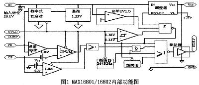
High-brightness (HB) LED driver control integrated chip MAXl680l/16802 basically meets the requirements of the actual LED driver key circuit, can be used for high-brightness illumination and display applications, can be AC-rectified voltage input of 85 ~ 265V, need to adjust the LED current with precision An on-chip error amplifier and a 1% accuracy reference can be used. A wide range of brightness adjustments can also be achieved with on-chip PWM brightness adjustment.
The internal functions of the MAXl6801/16802 are shown in Figure 1.
The driving circuit of a single LED chip is shown in Figure 2.
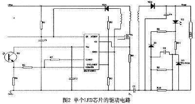
A description of the function between the various ports of the circuit:
UVLO/EN: External programmable undervoltage lockout. UVLO sets the input startup voltage. Connecting UVLO to GND disables device operation. DIM/FB: Low frequency PWM dimming input / error amplification inverting input. COMP: Error amplifier output. In high brightness LED current regulation applications, the compensation component is connected between DIM/FB and COMP.
CS: Current sense signal connection for current regulation. The ring current-sense resistor is high-end. The 甩 filter can be removed from the leading edge of the RC filter. GND: Power ground. NDRV: External N-channel MO-SET gate connection. Vcc: Gate drive power supply. The internal is obtained by stepping down the IN. Connect a decoupling capacitor of 10nF or more between Vcc and GND. IN: IC power supply. Connect a decoupling capacitor above 10nFt between IN and GND. In the bootstrap mode, the MAXl6801 can be connected to a startup resistor from the input supply and IN. The bias winding power supply is connected to this point. For the MAXl6802, the IN is directly connected to the +10.8~+24V power supply.
4.2 PWM control circuit for a single LED chip
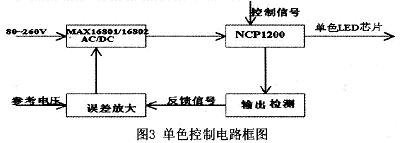
Since the electro-optical conversion efficiencies of the red, green and blue LEDs are inconsistent, and the ratios of the red, green and blue primary colors are different when the light is mixed, the three color chips are separately modulated. The modulation chip is NCP-1200, which is a current-mode PWM controller from ON Semiconductor. Its application circuit requires only a few external components to make the design more compact. In addition, the chip integrates an output short-circuit protection circuit, which further reduces the cost. There are two types of feedback in the module: the first is the output voltage feedback, the output voltage sample value VSS is compared with the set value provided by the microcontroller, the voltage of the anode of the NCPl200 chip is controlled by the optocoupler, and the pulse of the output of the DRV pin is adjusted. Width to control the on and off time of the FET, so as to achieve the purpose of adjusting the output voltage value. The other feedback is the current limit feedback. When the sampled output current value ISS exceeds the maximum current limit value IPWM provided by the MCU, the comparator outputs a positive voltage to make the optocoupler fully conductive, and the FB pin voltage is pulled low, so that the NCP1200 outputs The PWM pulse width is reduced to achieve the purpose of current limiting. The current limit feedback does not work when the output current is less than the current limit provided by the microcontroller.
The block diagram of the monochrome control circuit is shown in Figure 3.
4.3 Real-time control of three primary color circuits
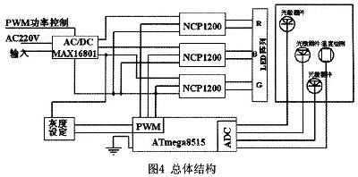
In the control of the NCPl200, the ATmega8515 microcontroller is used. The input of ATmega8515 is user setting and temperature feedback and light intensity feedback. The output is the control information of PWM modulation pulse width in NCPl200.
The I/O port of the ATmega8515 can be used to set multiple control signals through the keyboard and dial switch. It is also possible to program the input of the full-color pulse width ratio into a single chip according to the calculated three-color light mixing ratio and the three-chip PWM meter to realize rapid color change.
4.4 Overall framework
In order to ensure that the LED is compensated for the attenuation of the light intensity caused by the heat, temperature feedback and light intensity feedback are added to the output to correct the light attenuation caused by the heat. The overall structure is shown in Figure 4.
5 Conclusion
In order to realize high-power full-color LED lighting, the design of the RG-BLED lighting driver with power supply for the open-light power supply with MAXl6801/16802 as the core and PWM, respectively, for the red, green and blue primary color chips is designed. This design considers the practical problems of LEDI chip in the process of temperature rise, such as luminescence attenuation, output wavelength drift, lumen attenuation, and corresponding compensation. A certain degree of gray scale adjustment is achieved. Under the control system with ATmega8515 single chip as the core, the temperature sensor and photoelectric sensor are used as the feedback information source to realize adaptive control. Experiments prove that this driving circuit works well, can achieve a certain degree of multi-color lighting, applied to outdoor lighting and landscape lighting.
Combo GPS Antenna SPECIFICATIONS:
Center Frequency: 1575.42±1MHz
Band Width: CF±5MHz
Polarization: RHCP
Gain: 5dBic(Zenith)
V.S.W.R: <1.5
Impendance: 50Ω
Axial Ratio: 3dB(max)
Gain:28±2dBi
Noise Figure: <1.5
Ex-band Attenuation: 12dB@CF+50MHz/16dB@CF-50MHz
V.S.W.R: <2.0
Supply Voltage: 2.2~5V DC
Current Consumption: 5~15mA
GSM Antenna
Frequency Range: 824~960MHz/1710~2170MHz
V.S.W.R(min): <2.5
Polarization: Linear
Gain: 2dBi
Impendance: 50Ω
Cable: RG174
Connector: SMA/MCX/FAKRA or others
Radome Material: ABS
Mounting Method: Magnet
Operating Temperature: -40℃~+85℃
Relative Humidity: Up to 95%
Vibration: `10 to 55Hz with 1.5mm amplitude 2hours
Environmentally Friendly: ROHS Compliant
Combo GPS Antenna PICTURES:


Combo GPS Antenna
Combo GPS Antenna,GPS Combo Antenna,GSM GPS Antenna,GPS Glonass Antenna
Shenzhen Yetnorson Technology Co., Ltd. , http://www.yetnorson.com